Bently Nevada 330130-080-10-05 Spare for 3300 XL Automation
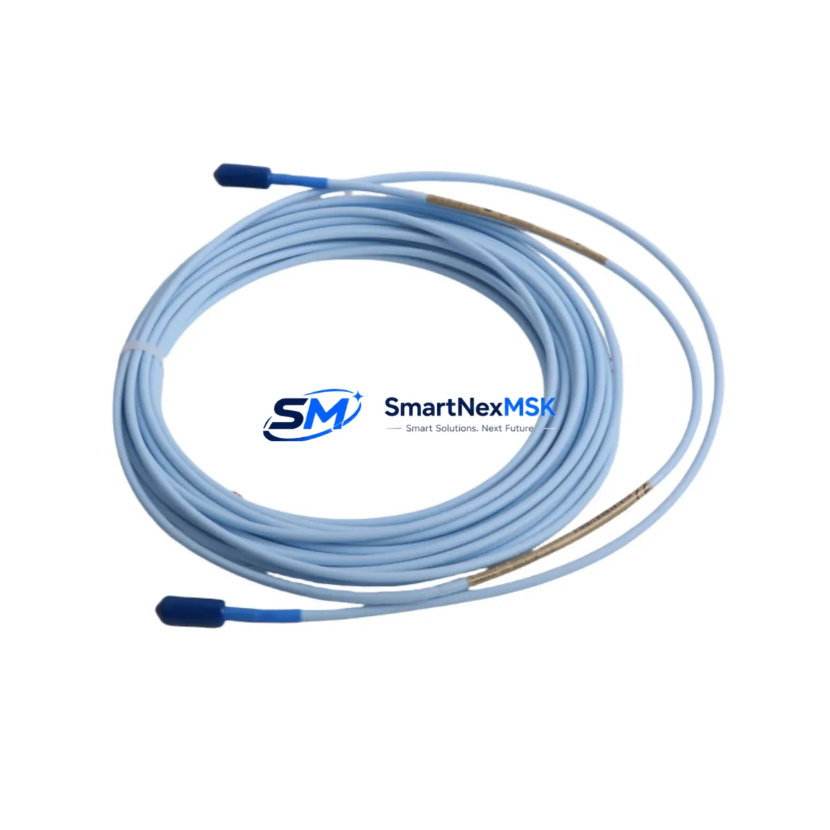
The Bently Nevada 330130-080-10-05 is an 8-meter proximity extension cable engineered for the 3300 XL continuous vibration monitoring system. As a maintenance-ready original spare, this cable serves as the critical signal link between the 3300 XL proximity transducer and the monitoring system’s signal conditioning modules. In rotating machinery protection applications — turbines, compressors, pumps, and gearboxes — cable integrity is non-negotiable. A degraded or failed extension cable introduces signal noise, triggers false alarms, or causes complete loss of vibration data, all of which translate directly into unplanned downtime and production loss.
For maintenance engineers managing aging machinery protection systems, stocking the 330130-080-10-05 as a certified spare eliminates the most common single point of failure in the 3300 XL measurement chain. This cable is fully compatible with the 3300 XL 8mm proximity transducer (330130-080-00-00 series) and the 3300 XL proximitor sensor, and it integrates directly with the 3300/16 and 3300/20 rack-mounted monitoring modules without modification.
Spare Maintenance Table
| Part Number | 330130-080-10-05 |
| Brand | Bently Nevada |
| Series | 3300 XL |
| Product Type | Proximity Extension Cable |
| Cable Length | 8 metres (26.2 ft) |
| Connector Type | MIL-C-5015 style, coaxial, armoured |
| Compatible Transducer | 3300 XL 8mm Proximity Transducer (330130 series) |
| Compatible Proximitor | 3300 XL Proximitor Sensor (330180 series) |
| Compatible Monitors | 3300/16, 3300/20, 3500/42M |
| Operating Temperature | -40°C to +85°C |
| Installation Environment | Industrial — suitable for high-vibration, high-temperature machinery enclosures |
| Origin | USA |
| Condition | Original, New / Tested |
| Warranty | 12 Months |
| Lead Time | In Stock — Ready to Ship |
Maintenance Planning for Continuous Operation
When a 330130-080-10-05 extension cable is scheduled for replacement during planned maintenance or emergency callout, experienced maintenance engineers treat the event as an opportunity to inspect the entire 3300 XL measurement chain. The extension cable does not operate in isolation — it is one node in a signal path that begins at the probe tip and ends at the rack-mounted monitor input card.
Start with the 3300 XL 8mm proximity transducer (330130-080-00-00). Check the probe tip for mechanical damage, thread condition, and gap setting. A worn or mis-gapped probe will produce erratic output regardless of cable quality. Next, inspect the 3300 XL Proximitor Sensor (330180-A1-B1-C1-D1 series) — the signal conditioning module that powers the probe and converts gap distance to a DC voltage. Verify its mounting, connector seating, and output voltage under static conditions.
At the rack level, confirm that the 3300/16 or 3300/20 monitor module input card is free of corrosion on its backplane connectors. If the system uses a 3500 Series rack, inspect the 3500/42M proximitor I/O module and its terminal block wiring for loose terminations. Loose terminals at the I/O module are a frequent cause of intermittent alarms that are misdiagnosed as cable faults.
Power supply integrity is equally important. The 3300 XL system power supply module provides the regulated DC bias voltage that drives the entire proximity measurement loop. A power supply with marginal output voltage will cause all channels to read incorrectly. Check output voltage under load and compare against the module’s specification label.
For facilities running the 3500 Series machinery protection system alongside legacy 3300 XL hardware, also verify the 3500/20 rack interface module and its communication link to the plant DCS or historian. Signal integrity issues at the communication layer can mask genuine mechanical faults. Where Modbus or FOUNDATION Fieldbus integration is in use, inspect the communication gateway module and its termination resistors.
In control cabinet inspections, check the terminal blocks and cable glands at the junction box where the extension cable enters the cabinet. Moisture ingress at this point is a leading cause of cable insulation degradation. Replace any corroded terminal blocks and re-seal cable glands as part of the same work order. Finally, verify that all cable shields are grounded at one end only — double-grounded shields introduce ground loops that corrupt the proximity signal.
Procurement engineers should note that the 330130-080-10-05 is a long-lead item from the OEM channel. Maintaining a minimum of two units in the site spare parts store eliminates the risk of extended downtime while awaiting factory delivery. Pair this with a stocked 3300 XL Proximitor Sensor and at least one spare 3300/16 monitor input card to cover the three most common failure modes in the 3300 XL measurement chain.
Site Replacement Workflow
Step 1 — Isolate and de-energise. Follow your site LOTO procedure. Remove the proximitor sensor connector from the extension cable at the field junction box. Do not disconnect the probe from the extension cable in the field unless the probe itself is being replaced — unnecessary disconnection risks damaging the probe thread.
Step 2 — Document the existing installation. Photograph the cable routing, connector orientation, and any cable ties or clamps before removal. This is especially important in congested machinery enclosures where re-routing errors can introduce mechanical stress on the new cable.
Step 3 — Install the 330130-080-10-05 replacement cable. Route the cable following the original path. Avoid sharp bends within 150mm of either connector. Torque connectors to the manufacturer’s specification — over-tightening damages the coaxial centre pin and under-tightening causes intermittent contact.
Step 4 — Verify gap and output voltage. Re-energise the proximitor sensor and measure the output voltage at the monitor input. For a standard 8mm probe at the nominal 1.0mm gap, the expected output is approximately -10.0 VDC. Adjust the probe gap if the output is outside the ±0.5V acceptance band.
Step 5 — Confirm alarm and trip setpoints. Before returning the machine to service, verify that the monitor’s alert and danger setpoints are correctly configured and that the channel is not in bypass mode. A channel left in bypass after maintenance is a common cause of undetected machinery faults.
Step 6 — Update maintenance records. Log the replacement date, cable serial number, measured gap voltage, and technician name. This data supports future condition-based maintenance decisions and warranty claims.
Spare Parts Support FAQ
Q: Is the 330130-080-10-05 compatible with both the 3300 XL and 3500 Series systems?
A: The 330130-080-10-05 is designed for the 3300 XL measurement chain. It is compatible with 3300 XL 8mm proximity transducers and 3300 XL Proximitor Sensors. For 3500 Series applications, verify the specific I/O module and cable specification before ordering — some 3500 Series configurations use different cable assemblies.
Q: What is included in the 12-month warranty?
A: Every 330130-080-10-05 shipped by SMARTNEXMSK is covered by a 12-month warranty against manufacturing defects and electrical failure under normal operating conditions. Each unit is tested prior to dispatch. Warranty claims are supported with replacement or refund at our discretion.
Q: How do I verify the cable condition before installation?
A: Perform a continuity check on the centre conductor and shield using a calibrated multimeter. Measure insulation resistance between the centre conductor and shield — values below 100 MΩ indicate moisture ingress or insulation damage. Visually inspect both connectors for bent pins, corrosion, or cracked insulation before installation.
Q: What is the recommended spare parts holding strategy for the 3300 XL system?
A: For critical rotating machinery, maintain a minimum of two extension cables (330130-080-10-05), one Proximitor Sensor (330180 series), and one spare monitor input card per monitored machine train. For facilities with multiple identical machine trains, a shared pool of three to five cables is typically sufficient to cover emergency replacements without excessive inventory cost.
© 2026 SMARTNEXMSK. All rights reserved.
Original Source: https://smartnexmsk.com
Contact: sales@smartnexmsk.com | +86 18259474341


