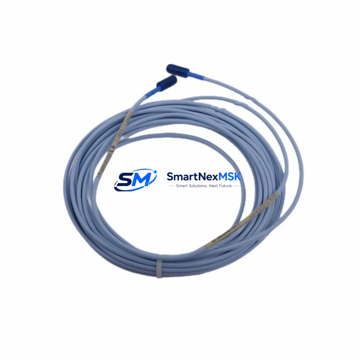
Bently Nevada 330130-085-00-05 Retrofit Extension Cable for 3300 XL Proximity Systems
The Bently Nevada 330130-085-00-05 is an 8.5-metre (28 ft) extension cable engineered for the 3300 XL 8mm Proximity System — one of the most widely deployed vibration and position monitoring platforms in rotating machinery applications worldwide. As legacy 3300 XL installations age and OEM support windows narrow, sourcing a verified, retrofit-ready replacement cable becomes a critical path item for maintenance engineers managing turbines, compressors, pumps, and gearboxes in continuous-process environments.
This cable serves as the signal conduit between the 3300 XL 8mm proximity probe (such as the 330103-00-08-10-02-00 or 330104 series) and the 3300 XL proximitor/oscillator (driver), completing the three-component measurement chain that Bently Nevada’s eddy-current sensing architecture requires. Maintaining the correct cable length — 8.5 m in this configuration — is essential for preserving the system’s calibrated sensitivity and gap voltage output. Substituting an incorrect cable length will shift the linear range and invalidate the existing calibration curve stored in the 3500/42M or 3500/40M monitor modules.
Upgrade Compatibility Table
| Parameter | 330130-085-00-05 (This Unit) | Retrofit / Replacement Notes |
|---|---|---|
| Cable Length | 8.5 m (28 ft) | Must match original system design; mismatched length alters gap voltage calibration |
| Compatible Probe Series | 3300 XL 8mm (330103 / 330104 series) | Verify probe part number before ordering; 5mm probes use a different cable family |
| Compatible Driver/Proximitor | 3300 XL Proximitor (330180 series) | Confirm driver model; 3300 NSv and 3500 series use different connector pinouts |
| Monitor Compatibility | 3500/40M, 3500/42M, 3500/45, 3500/46M | Check rack slot assignment and channel configuration in System 1 software |
| Connector Type | Standard BNC / coaxial per 3300 XL spec | Inspect field-end connector for corrosion or mechanical damage before re-use |
| Installation Requirement | DIN rail / conduit routing, IP-rated junction box recommended | Maintain minimum bend radius; avoid routing near high-voltage power cables |
| Communication / Protocol | Analog signal (passive cable — no protocol) | Signal integrity verified by gap voltage check at proximitor output terminal |
| Replacement Recommendation | Direct drop-in for 330130-085-00-05 | No firmware or configuration change required in 3500 rack after cable swap |
| Commissioning Check | Gap voltage: −10 VDC ± 0.5 V at nominal gap | Verify with calibrated voltmeter at proximitor output before returning to service |
| Warranty | 12-Month Warranty — covers manufacturing defects and signal integrity under normal operating conditions | |
Retrofit Planning for Existing Automation Systems
When a 3300 XL proximity system reaches end-of-life or a cable fails in service, the retrofit scope typically extends well beyond a single component. A thorough upgrade plan should account for the full measurement chain and the monitoring infrastructure it feeds. In most installations, the 330130-085-00-05 extension cable connects to a 330103-00-08-10-02-00 proximity probe at the machine end and terminates at a 330180-X1-05 proximitor/oscillator mounted in a field junction box or directly on the machinery skid. Both components should be inspected — and ideally replaced simultaneously — to avoid introducing a new cable into a degraded probe or driver assembly.
The proximitor output feeds into a 3500 Series monitoring rack, typically housing a 3500/20 rack interface module, a 3500/15 power supply module, and one or more 3500/42M four-channel dynamic pressure and position monitor cards or 3500/40M proximitor I/O modules. Before pulling the old cable, engineers should document the existing gap voltage readings on each channel using the front-panel display or System 1 Evolution condition monitoring software, so post-installation values can be compared against the baseline.
For plants migrating from older 3300 RAM (Rack Architecture Monitor) systems to the current 3500 platform, the cable replacement is often the first physical step in a phased modernization. The 3300 XL cable family is mechanically compatible with the new rack’s I/O module terminal blocks, but the 3500/20 RIM configuration must be updated in the rack’s non-volatile memory using a Rack Configuration Software (RCS) session over the RS-232 or Ethernet service port. If the plant also operates Keyphasor® modules (3500/25) for phase reference, their cable routing and termination should be verified at the same time to avoid phase-reference errors after the rack is returned to service.
In control cabinet upgrades where the 3500 rack shares an enclosure with a DeltaV S-series controller or a ControlLogix L7x rack, cable segregation between the low-level analog vibration signals and the 24 VDC I/O wiring is mandatory. Use shielded conduit or dedicated cable trays, and ground the cable shield at one end only — typically at the proximitor junction box — to prevent ground loops that would appear as noise on the vibration channel. A 3500/92 communication gateway module or a TDI (Transient Data Interface) card may also be present in the rack; their Ethernet or Modbus TCP links to the plant DCS should be tested after the cable swap to confirm that the monitoring data stream is uninterrupted.
Downtime Control During System Migration
Replacing a proximity system extension cable on a running machine train requires careful coordination between the reliability, instrumentation, and operations teams. The preferred approach is a hot-standby swap where the new 330130-085-00-05 cable is pre-routed and terminated at both ends before the old cable is disconnected. This minimizes the window during which the channel is in a “not OK” state and the 3500 rack may generate a trip or alert output to the plant safety system.
Before breaking any connection, place the affected monitor channel into bypass mode using the front-panel keyswitch or the System 1 software interface. This suppresses the channel’s vote in any two-out-of-three (2oo3) or one-out-of-two (1oo2) voting logic that protects the machine. Confirm with the control room that the bypass is acknowledged and logged in the plant’s management of change (MOC) system. Once the new cable is connected and the gap voltage is verified within specification, remove the bypass and confirm that the channel returns to “OK” status before closing the work order.
For planned turnaround outages, the cable replacement can be combined with a full probe-and-driver calibration check, connector re-termination, and junction box inspection. Stocking a complete spare set — probe, extension cable, and proximitor — ensures that any component found out-of-tolerance during the outage can be replaced immediately without extending the shutdown. All replaced components should be tagged, serialized, and entered into the plant’s CMMS (such as SAP PM or Maximo) with the as-found and as-left gap voltage values recorded for trend analysis.
Retrofit Support FAQ
Q1: Is the 330130-085-00-05 a direct replacement for the original Bently Nevada cable, or does it require recalibration?
A: It is a direct drop-in replacement. The cable is a passive component; no firmware update or rack reconfiguration is required. After installation, verify the gap voltage at the proximitor output terminal (target: −10 VDC ± 0.5 V at nominal gap) and compare against the channel’s historical baseline. If the reading is within tolerance, the system is ready to return to service without a full recalibration.
Q2: What wiring checks should be performed before and after the cable swap?
A: Inspect both connector ends for corrosion, bent pins, and damaged insulation. Measure the cable’s DC resistance and insulation resistance (IR) before installation. After connection, check the gap voltage at the proximitor output and confirm the “OK” LED is illuminated on the 3500 monitor card. Also verify that the shield drain wire is grounded at one end only to prevent ground-loop noise.
Q3: Can this cable be used with the newer 3500 NSv or Orbit 60 Series monitors?
A: The 330130-085-00-05 is designed for the 3300 XL 8mm proximity system. While the 3500 rack accepts 3300 XL probes and cables via compatible I/O modules, the Orbit 60 Series uses a different sensor architecture. Confirm the target monitor’s I/O module part number and consult the system’s wiring diagram before ordering.
Q4: What does the 12-month warranty cover, and what is the return process?
A: The 12-month warranty covers manufacturing defects and signal integrity failures under normal operating conditions. It does not cover damage from improper installation, over-bending, chemical exposure, or mechanical impact. To initiate a warranty claim, contact sales@smartnexmsk.com with the order number, installation date, and a description of the fault. Replacement units are typically dispatched within 3 business days of claim approval.
© 2026 SMARTNEXMSK. All rights reserved.
Original Source: https://smartnexmsk.com
Contact: sales@smartnexmsk.com | +86 18259474341


