Bently Nevada 330130-085-01-00 Maintenance-Ready Spare for 3300 XL Automation
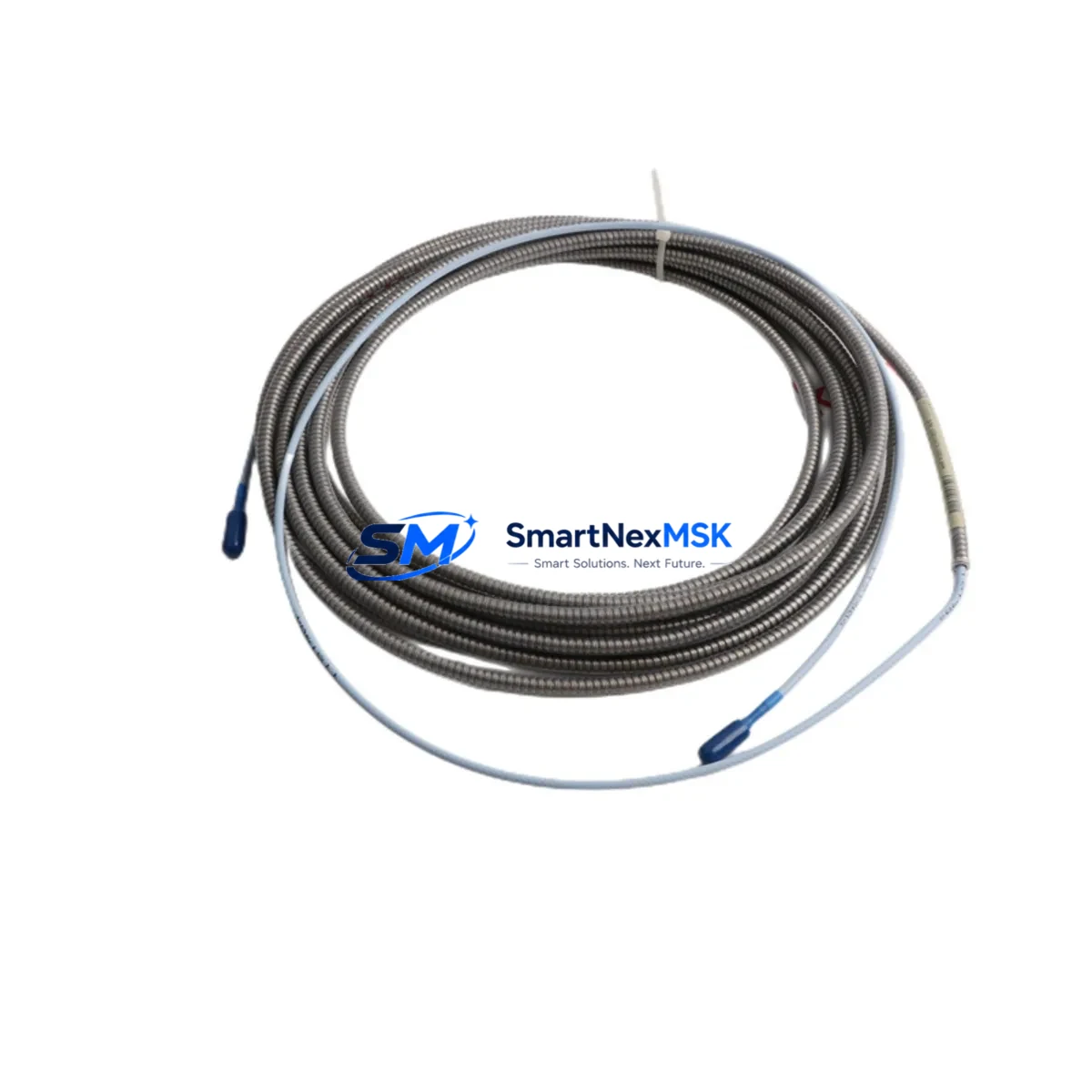
The Bently Nevada 330130-085-01-00 is an 8.5-metre extension cable engineered for the 3300 XL series proximity transducer system — one of the most widely deployed vibration and position monitoring platforms in rotating machinery protection. Designed to bridge the gap between the proximitor/driver and the eddy-current probe, this cable is a precision-matched, shielded interconnect that preserves signal integrity across the full measurement chain. For maintenance engineers managing turbines, compressors, pumps, and gearboxes in continuous-process plants, having a verified spare of the 330130-085-01-00 on the shelf is a fundamental element of any credible machinery protection strategy.
Unplanned downtime caused by cable degradation — whether from mechanical abrasion, connector corrosion, thermal cycling, or chemical exposure — is one of the most preventable failure modes in vibration monitoring. A single failed extension cable can render an entire monitoring channel blind, triggering nuisance trips or, worse, masking a developing fault. Stocking the 330130-085-01-00 as a maintenance-ready spare eliminates this risk and supports rapid channel restoration during planned outages or emergency callouts.
Each unit supplied by SMARTNEXMSK is sourced from verified industrial channels, individually inspected, and dispatched with a 12-month warranty. We support long-term supply continuity for legacy 3300 XL installations where OEM availability may be constrained.
Spare Maintenance Table
| Parameter | Specification |
|---|---|
| Part Number / SKU | 330130-085-01-00 |
| Brand | Bently Nevada (Baker Hughes) |
| Series | 3300 XL Proximity Transducer System |
| Product Type | Extension Cable |
| Cable Length | 8.5 metres (085 designation) |
| Connector Type | MIL-spec coaxial, compatible with 3300 XL proximitor and probe |
| Shield Configuration | Double-shielded coaxial for EMI/RFI rejection |
| Compatible Probes | 330100, 330101, 330103 series eddy-current probes |
| Compatible Proximitors | 330180, 330185 series 3300 XL proximitor drivers |
| System Compatibility | 3300 XL, 3300/16, 3500 series (with appropriate driver) |
| Application Environment | Turbines, compressors, pumps, gearboxes, motors |
| Operating Temperature | -40°C to +85°C (cable); connector per MIL-C-5015 |
| Installation | Direct replacement; no recalibration required if system gap voltage is verified post-installation |
| Origin | USA |
| Warranty | 12 Months — covers manufacturing defects and electrical performance |
| Condition | New / Tested Industrial Spare |
| Lead Time | In-stock; ships within 1–3 business days |
Maintenance Planning for Continuous Operation
When a 330130-085-01-00 extension cable is flagged for replacement during a scheduled outage or emergency intervention, experienced maintenance engineers treat the event as a trigger for a broader channel audit. The extension cable sits at the centre of a measurement chain that includes multiple interdependent components — and a cable swap is the ideal moment to verify the health of each.
Begin with the 330180 or 330185 proximitor driver, which conditions the raw eddy-current signal from the probe. Check the driver’s output voltage (typically –18 VDC gap voltage at nominal air gap) and confirm the power supply rail — usually a dedicated –24 VDC instrument power supply or the rack-mounted power module within the 3300/16 or 3500 monitor chassis — is within tolerance. A degraded power supply can mimic cable faults and cause repeat failures.
Inspect the 330100 or 330103 series eddy-current probe at the machine end. Check the probe tip for mechanical damage, contamination, or thermal discolouration. Measure probe resistance and compare against baseline. If the probe is approaching end-of-life, replace it concurrently with the extension cable to avoid a second outage within the same maintenance cycle.
Verify the integrity of the 3300/16 or 3500 series monitor card in the rack. Confirm that the channel is not showing latched alarms or diagnostic faults that predate the cable failure. If the monitor card has been in service for more than ten years, consider scheduling a card swap during the next planned outage — spare monitor cards such as the 3300/16 Dual Voting or 3500/42M position monitor should be part of any mature spare parts inventory.
At the terminal cabinet level, inspect the junction box or field terminal assembly where the extension cable connects to the field wiring. Check for corrosion on terminal blocks, verify cable gland integrity, and confirm that the cable routing does not expose the coaxial assembly to mechanical pinch points or excessive heat sources. If the installation uses signal isolators or barriers (common in Zone 1/Zone 2 hazardous area installations), verify that the isolator output is within specification — a degraded isolator can corrupt the gap voltage reading even after a cable replacement.
For plants running Bently Nevada System 1 or System 1 Evolution condition monitoring software, confirm that the channel configuration reflects the correct probe/cable/proximitor combination after the replacement. Update the asset record and re-baseline the gap voltage and vibration trend data to establish a clean post-maintenance reference.
Finally, review the fuse or circuit protection on the instrument power rail feeding the proximitor. A blown or degraded fuse is a common root cause of apparent cable or proximitor failures and takes less than two minutes to verify. Keeping a stock of the correct-rated fuses alongside the 330130-085-01-00 spare ensures that the full restoration workflow can be completed without a secondary parts search.
Site Replacement Workflow
Step 1 — Isolate and document. Before disconnecting the existing cable, record the current gap voltage reading from the monitor display or System 1 software. This baseline is essential for post-installation verification. Note the alarm and danger setpoints for the channel.
Step 2 — Disconnect and inspect connectors. Remove the extension cable from both the probe and the proximitor. Inspect the connector pins and sockets for corrosion, bent contacts, or contamination. Clean with isopropyl alcohol if required. Do not use abrasive tools on the connector contacts.
Step 3 — Install the 330130-085-01-00. Route the new cable following the original cable path. Avoid sharp bends below the minimum bend radius. Secure with cable ties at the same intervals as the original installation. Hand-tighten connectors to the specified torque — over-tightening damages the MIL-spec connector threads.
Step 4 — Verify gap voltage. With the machine at rest, confirm that the gap voltage at the monitor input is within the linear range (typically –10 VDC ±1 VDC for a standard 5mm probe/cable/proximitor combination). Adjust the probe air gap if necessary. Do not return the channel to service until the gap voltage is confirmed within the acceptable window.
Step 5 — Functional test and return to service. Clear any latched alarms on the monitor card. Confirm that the channel is reading correctly in System 1 or the local display. Document the replacement in the maintenance management system (CMMS) and update the spare parts inventory to trigger reorder of a replacement 330130-085-01-00.
This workflow is applicable to both planned maintenance windows and emergency callouts. The total replacement time for a competent technician is typically 30–60 minutes, making the 330130-085-01-00 one of the most cost-effective spares in a rotating machinery protection programme.
Spare Parts Support FAQ
Q1: Is the 330130-085-01-00 a direct replacement for the original Bently Nevada cable, and will it require system recalibration?
Yes. The 330130-085-01-00 is a specification-matched replacement for the original Bently Nevada cable of the same part number. Because the cable is a passive interconnect (it does not contain active electronics), no recalibration of the monitor card is required. However, you must verify the gap voltage after installation to confirm that the probe air gap has not shifted during the cable swap. If the gap voltage is outside the linear range, adjust the probe position accordingly before returning the channel to service.
Q2: What is the recommended inventory strategy for 330130-085-01-00 cables in a multi-machine plant?
For plants with three or more 3300 XL monitoring channels, we recommend holding a minimum of two spare cables per cable length in use. The 330130-085-01-00 (8.5m) is a common length for mid-range installations. If your plant also uses shorter runs (e.g., 330130-040-01-00 at 4.0m) or longer runs (e.g., 330130-120-01-00 at 12.0m), maintain at least one spare of each length. Cables should be stored in a dry, temperature-controlled environment and inspected annually for connector corrosion.
Q3: How does SMARTNEXMSK verify the condition of the 330130-085-01-00 before shipment?
Each 330130-085-01-00 unit undergoes a pre-shipment inspection that includes visual examination of the cable jacket, connector pins, and shield termination, as well as a continuity and insulation resistance check. Units that do not meet specification are quarantined and not dispatched. All units are shipped with a 12-month warranty covering manufacturing defects and electrical performance. A test report is available on request for critical applications.
Q4: Can the 330130-085-01-00 be used with 3500 series monitors as well as 3300 XL?
The 330130-085-01-00 is designed and specified for the 3300 XL proximity transducer system. Compatibility with 3500 series monitors depends on the specific proximitor driver and probe combination in use. The 3500 series typically uses the 330180 or 330185 proximitor, which is also used in 3300 XL configurations, so cross-compatibility is common in practice. However, always verify the complete probe/cable/proximitor combination against the Bently Nevada system specification sheet for your specific monitor card before installation. Contact our technical team at sales@smartnexmsk.com for compatibility confirmation if required.
© 2026 SMARTNEXMSK. All rights reserved.
Original Source: https://smartnexmsk.com
Contact: sales@smartnexmsk.com | +86 18259474341


