Bently Nevada 330130-085-03-05 Maintenance-Ready Spare for 3300 XL Automation
The Bently Nevada 330130-085-03-05 is an original 8.5-metre proximity extension cable engineered for the 3300 XL Series continuous vibration monitoring system. In rotating-machinery protection environments — turbines, compressors, pumps, and gearboxes — this cable forms the critical signal path between the 3300 XL proximitor/sensor and the monitoring rack. A degraded or failed extension cable is one of the most common root causes of false Keyphasor® trips, erratic proximity readings, and unplanned shutdowns. Stocking a verified original spare eliminates the diagnostic ambiguity that arises when cable integrity is unknown, and it allows maintenance teams to restore full monitoring capability within a single shift window.
Spare Maintenance Table
| Part Number | 330130-085-03-05 |
| Brand | Bently Nevada |
| Series | 3300 XL Proximity System |
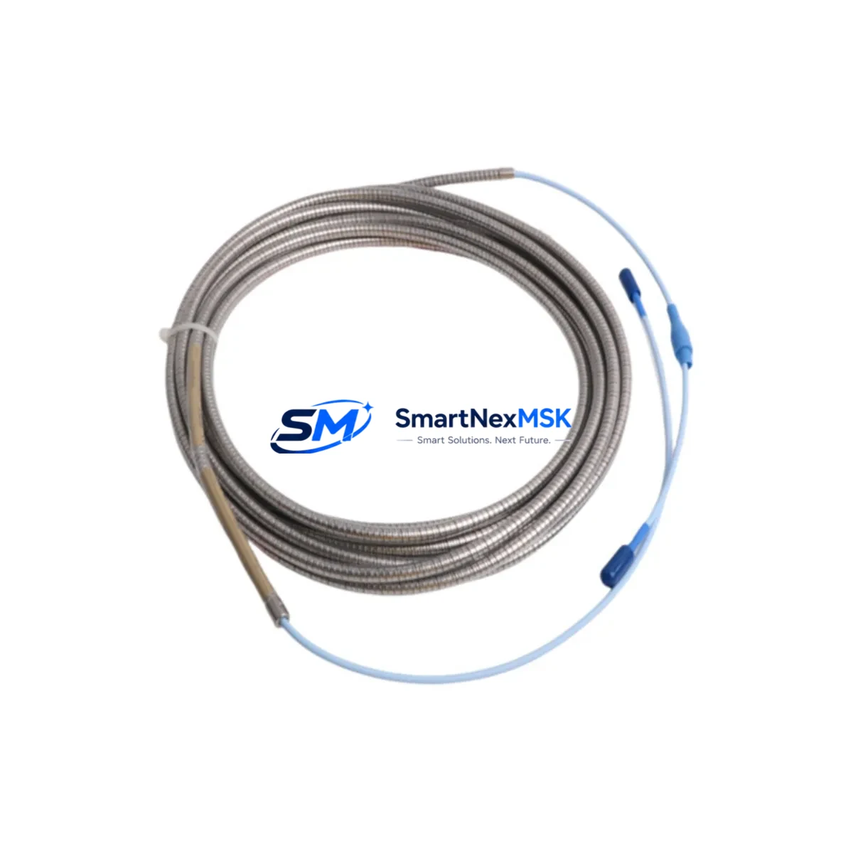
| Product Type | Proximity Extension Cable |
| Cable Length | 8.5 m (28 ft) |
| Connector Type | MIL-C-5015 style, armoured coaxial |
| System Compatibility | 3300 XL 8mm, 11mm, 14mm Proximity Transducer Systems; 3500 Series (with adapter); compatible proximitor models 330180, 330185, 330190 |
| Signal Type | Eddy-current proximity, DC-coupled, -24 VDC bias |
| Operating Temperature | -40 °C to +121 °C |
| Installation Environment | Turbine bearing pedestals, compressor skids, pump bearing housings, gearbox monitoring points |
| Origin | USA (Original Bently Nevada) |
| Maintenance Recommendation | Inspect connectors and armour sheath at every planned outage; replace if insulation resistance < 100 MΩ or signal gap voltage deviates > ±0.5 VDC from baseline |
| Warranty | 12 Months |
| Shipping | Tested before dispatch; ESD-safe packaging |
Maintenance Planning for Continuous Operation
Effective vibration monitoring reliability depends on the integrity of every component in the measurement chain, not just the proximitor or the monitoring module. When a maintenance or reliability engineer schedules replacement of the 330130-085-03-05 extension cable, the same outage window should be used to inspect and, where necessary, replace adjacent components that share the same signal loop or control-cabinet circuit.
Begin with the 3300 XL proximitor/sensor assembly (e.g., 330103-00-08-10-02-00 or 330104 series) at the bearing housing end. Connector corrosion or mechanical damage to the sensor tip is frequently found alongside cable degradation in high-temperature or high-humidity environments. Next, verify the 3300 XL monitor module in the rack — models such as the 3300/16 or 3300/20 — for correct gap voltage display and alarm setpoint integrity after cable replacement.
In the same control cabinet, check the 3300 XL power supply module (e.g., 3300/05) for output voltage stability; a marginal power supply can mask itself as a cable fault. Inspect the Keyphasor® module (330180 or 3500/17) and its dedicated extension cable if the machine uses phase-referenced vibration analysis, since Keyphasor signal loss will invalidate 1X/2X vector data across the entire monitoring system.
For systems integrated into a 3500 Series rack, confirm that the 3500/42M position monitor or 3500/40M proximitor I/O module termination boards are seated correctly and that field wiring terminal blocks show no signs of oxidation. Where the proximity signal feeds a DCS or safety PLC via a signal isolator or barrier (such as a Pepperl+Fuchs KFD2 series or MTL5000 series Zener barrier), test the barrier for correct output range after cable swap — a failed barrier can produce a healthy-looking gap voltage at the rack while delivering a corrupted 4–20 mA signal to the control system.
Finally, document the as-found and as-left gap voltage readings in the site maintenance management system (CMMS). Trending gap voltage over successive outages is the most reliable early indicator of shaft centreline migration or bearing wear, and it provides the data needed to justify proactive cable and sensor replacement before the next planned shutdown.
Site Replacement Workflow
Step 1 — Isolation and permit: Obtain a hot-work or electrical isolation permit per site procedure. De-energise the proximitor supply at the 3300 XL power supply module or at the 3500 rack I/O card before disconnecting any field wiring.
Step 2 — As-found documentation: Record the existing gap voltage (typically –10.0 to –18.0 VDC for 8 mm systems) and note any alarm or danger status on the 3300 XL monitor. Photograph connector condition at both the sensor end and the proximitor end.
Step 3 — Cable removal: Unscrew the MIL-style connectors at both ends. Inspect the armour sheath along its full run for kinks, crush damage, or chemical attack. If the conduit or cable tray shows signs of heat damage, address the root cause before installing the replacement.
Step 4 — Install 330130-085-03-05: Route the new cable following the original path. Avoid sharp bends below the minimum bend radius. Torque connectors to the manufacturer specification. Do not substitute with a non-original cable of different characteristic impedance, as this will shift the gap voltage calibration curve.
Step 5 — Commissioning check: Re-energise the proximitor supply and verify gap voltage is within the –10.0 to –18.0 VDC window at the nominal air gap. Confirm that the 3300 XL monitor displays a healthy status and that no spurious alarms are present. Log as-left readings.
Step 6 — System handover: Return the machine to service and update the CMMS with part number, installation date, and as-left gap voltage. Retain the replaced cable for failure analysis if the fault was intermittent.
Spare Parts Support FAQ
Q1: Is the 330130-085-03-05 compatible with both 3300 XL and 3500 Series monitoring racks?
The 330130-085-03-05 is a native 3300 XL Series extension cable. It is directly compatible with 3300 XL proximitor models. Integration with 3500 Series I/O modules is possible using the appropriate 3500 series field wiring termination adapter; confirm the adapter part number against your rack configuration before ordering.
Q2: What is the recommended spare-holding strategy for this cable?
For critical rotating machinery (turbines, compressors), best practice is to hold a minimum of one spare per monitored bearing axis, plus one additional unit per machine train as a fast-response buffer. For non-critical pumps and fans, a shared pool of two to three cables per plant area is typically sufficient. Review spare holdings annually against machine criticality rankings.
Q3: How is the cable tested before shipment?
Each 330130-085-03-05 unit is inspected for connector integrity, insulation resistance, and coaxial continuity prior to dispatch. Units are packed in ESD-safe, moisture-resistant packaging with a test record. The 12-month warranty covers manufacturing defects and covers return or replacement at no additional freight cost.
Q4: Can this cable replace an older 330130-085-00-00 or similar legacy part number?
The -03-05 suffix designates the armour type and connector configuration. Cross-reference your existing cable label against the Bently Nevada 3300 XL compatibility matrix before substituting. In most 8 mm system installations the -03-05 variant is a direct drop-in replacement for earlier -00-00 and -01-00 suffix cables, but gap voltage recalibration should always be performed after any cable change to confirm system accuracy.
—
© 2026 SMARTNEXMSK. All rights reserved.
Original Source: https://smartnexmsk.com
Contact: sales@smartnexmsk.com | +86 18259474341


