Bently Nevada 330173-00-03-10-02-CN 3300 XL Maintenance-Ready Spare: Spare Parts Replacement and Industrial Downtime Risk Control
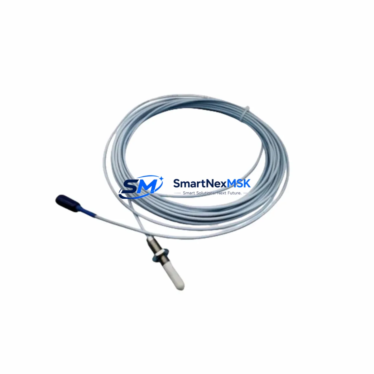
The Bently Nevada 330173-00-03-10-02-CN is an original 8mm eddy-current proximity probe engineered for the 3300 XL Series continuous vibration monitoring system. In rotating machinery protection applications — including steam turbines, compressors, pumps, and gearboxes — this probe is a primary sensing element responsible for shaft displacement, radial vibration, and eccentricity measurement. When this component degrades or fails, the entire protection loop is compromised, creating an unacceptable risk of undetected machinery damage and unplanned shutdown.
Stocking a verified original spare of the 330173-00-03-10-02-CN is a fundamental requirement for any maintenance program operating 3300 XL-based machinery protection systems. This unit ships tested, with full dimensional and electrical verification, and is backed by a 12-month warranty covering manufacturing defects and performance conformance.
Spare Maintenance Table
| Parameter | Specification |
|---|---|
| Part Number | 330173-00-03-10-02-CN |
| Brand | Bently Nevada |
| Series | 3300 XL |
| Type | Eddy-Current Proximity Probe (8mm) |
| Probe Tip Diameter | 8 mm |
| Cable Length | 3.0 m (integral cable) |
| Extension Cable Compatibility | 3300 XL Series Extension Cables (e.g. 330130-045-00-CN) |
| Driver / Proximitor Compatibility | 3300 XL 8mm Proximitor Sensor (e.g. 330180-X1-05) |
| Measurement Range | 0.25 mm – 2.25 mm (linear range) |
| Scale Factor | 7.87 V/mm (200 mV/mil) |
| Supply Voltage | -24 VDC (nominal) |
| Operating Temperature | -35°C to +177°C (probe tip) |
| Target Material | AISI 4140 steel or equivalent ferromagnetic alloy |
| Application Environment | Rotating machinery, turbine bearing housings, compressor trains, pump sets |
| Mounting | M10 x 1 thread, locknut included |
| Connector | Integral coaxial, CN-type termination |
| Compliance | API 670 (machinery protection standard) |
| Origin | USA |
| Warranty | 12 Months — manufacturing defects and performance conformance |
| Shipping | Tested and verified before dispatch; ESD-safe packaging |
Maintenance Planning for Continuous Operation
When a 330173-00-03-10-02-CN proximity probe is scheduled for replacement — whether during a planned outage, a predictive maintenance interval, or an emergency corrective action — maintenance and procurement engineers should treat the replacement as an opportunity to audit the entire vibration monitoring loop and adjacent control cabinet components.
Begin with the 3300 XL Proximitor Sensor (such as the 330180-X1-05 or equivalent 8mm driver module). The Proximitor converts the probe’s raw oscillator signal into a DC voltage proportional to gap distance; a probe that has been operating in a high-temperature or high-vibration environment may have stressed the driver’s input circuitry. Inspect the Proximitor for output drift, verify the bias voltage at the probe connector, and confirm the scale factor has not shifted beyond the ±1% tolerance band.
Next, inspect the extension cable assembly (typically a 330130-series cable matched to the probe’s integral cable length). Extension cables in rotating machinery environments are subject to continuous mechanical stress, oil contamination, and connector fretting. A degraded extension cable can introduce noise into the vibration signal that mimics actual shaft motion, leading to false alarms or, worse, masking real faults. Replace the extension cable if the outer jacket shows cracking, the connector shows corrosion, or the cable has been routed through a high-heat zone without conduit protection.
Within the control cabinet, verify the 3300 XL Monitor module (such as the 3300/16 or 3300/20 series rack-mounted monitor) for alarm setpoint integrity. Confirm that the OK relay output, the danger relay, and the buffered output terminals are all functioning correctly. If the monitor has been in service for more than five years without a calibration check, schedule a bench verification against a known gap simulator.
The power supply module feeding the 3300 XL rack — commonly a 3300/05 or equivalent -24 VDC rack power supply — should be load-tested during the outage window. Proximity probe systems are sensitive to supply voltage ripple; a power supply with degraded capacitors can introduce 50/60 Hz noise into the vibration channel. Check output voltage under full rack load and inspect for electrolytic capacitor bulging.
For installations where the 3300 XL rack interfaces with a DCS or safety system via 4–20 mA outputs or relay contacts, verify the signal isolator or barrier modules (such as Zener barriers or galvanic isolators in the IS circuit) for correct operation. Signal isolators in hazardous-area installations are often overlooked during probe replacement but are equally subject to aging and drift.
If the machinery protection system feeds a Bently Nevada System 1 or third-party condition monitoring platform via a communication module (e.g., Ethernet or serial gateway), confirm that the channel configuration in the software still matches the physical probe installation — gap, scale factor, and alarm thresholds. A probe swap without a corresponding software verification is a common source of post-maintenance nuisance trips.
Finally, inspect the terminal blocks and wiring within the junction box at the machinery skid. Vibration and thermal cycling cause terminal screws to loosen over time. Retorque all connections to the manufacturer’s specification, and replace any terminals showing signs of oxidation or arcing. This step costs minutes but prevents the majority of intermittent signal faults that are misdiagnosed as probe failures.
Site Replacement Workflow
Step 1 — Pre-replacement verification. Before removing the existing probe, record the current bias voltage (typically –10 VDC ± 1 V at the nominal air gap) and the buffered output voltage at the monitor. These baseline readings allow you to confirm the replacement probe is correctly installed and performing within specification before the machine is returned to service.
Step 2 — Mechanical removal. De-energize the Proximitor by disconnecting the extension cable at the junction box — do not disconnect at the probe tip under power, as the oscillator circuit can be damaged by an open-circuit condition. Remove the probe using the correct spanner on the locknut, taking care not to damage the probe tip or the target surface. Inspect the target area for scoring, pitting, or runout that may have contributed to the probe’s degradation.
Step 3 — Installation of 330173-00-03-10-02-CN replacement. Thread the new probe into the bracket, setting the initial air gap to the midpoint of the linear range (approximately 1.0–1.27 mm for an 8mm probe). Reconnect the extension cable and re-energize the Proximitor. Measure the bias voltage and adjust the gap until the output is within the specified linear range. Tighten the locknut to the specified torque.
Step 4 — System verification. Confirm the monitor’s OK status, verify alarm and danger setpoints are active, and perform a functional test of the relay outputs. If the installation is part of an API 670 SIL-rated protection system, complete the required proof-test documentation before returning the machine to service.
Step 5 — Documentation. Record the replacement in the maintenance management system (CMMS), including the new probe’s serial number, installation date, gap setting, and bias voltage. This data supports future predictive maintenance decisions and warranty claims.
Spare Parts Support FAQ
Q: Is the 330173-00-03-10-02-CN a direct drop-in replacement for earlier 3300 XL 8mm probes?
A: Yes. The 330173-00-03-10-02-CN is dimensionally and electrically compatible with the 3300 XL 8mm probe family. It uses the same M10 x 1 thread, the same coaxial connector standard, and the same 7.87 V/mm scale factor. It is compatible with all 3300 XL Proximitor Sensor models designed for 8mm probes. Always verify the extension cable length and connector type match your existing installation before ordering.
Q: What is the recommended spare parts inventory strategy for this probe?
A: For critical rotating machinery (turbines, compressors, large pumps), industry best practice is to maintain a minimum of two spare probes per monitored machine, stored in ESD-safe packaging in a climate-controlled environment. For facilities with multiple 3300 XL-equipped machines, a pooled inventory of 4–6 units is typically sufficient to cover both planned maintenance and emergency corrective replacements without excessive capital tied up in spares.
Q: How is each unit tested before shipment?
A: Every 330173-00-03-10-02-CN unit undergoes electrical continuity verification, oscillator frequency check, and bias voltage output test against a calibrated gap simulator prior to dispatch. Units that do not meet Bently Nevada’s published specification are rejected. A test report is available upon request for quality-critical installations.
Q: What does the 12-month warranty cover?
A: The 12-month warranty covers manufacturing defects, premature electrical failure under normal operating conditions, and non-conformance to published performance specifications. It does not cover damage resulting from incorrect installation, operation outside the specified temperature or voltage range, or physical damage to the probe tip or cable. Warranty claims are processed with return of the defective unit and provision of installation documentation.
© 2026 SMARTNEXMSK. All rights reserved.
Original Source: https://smartnexmsk.com
Contact: sales@smartnexmsk.com | +86 18259474341


