Bently Nevada 330180-50-00 Retrofit-Ready Proximitor Sensor for 3300 XL Control Systems
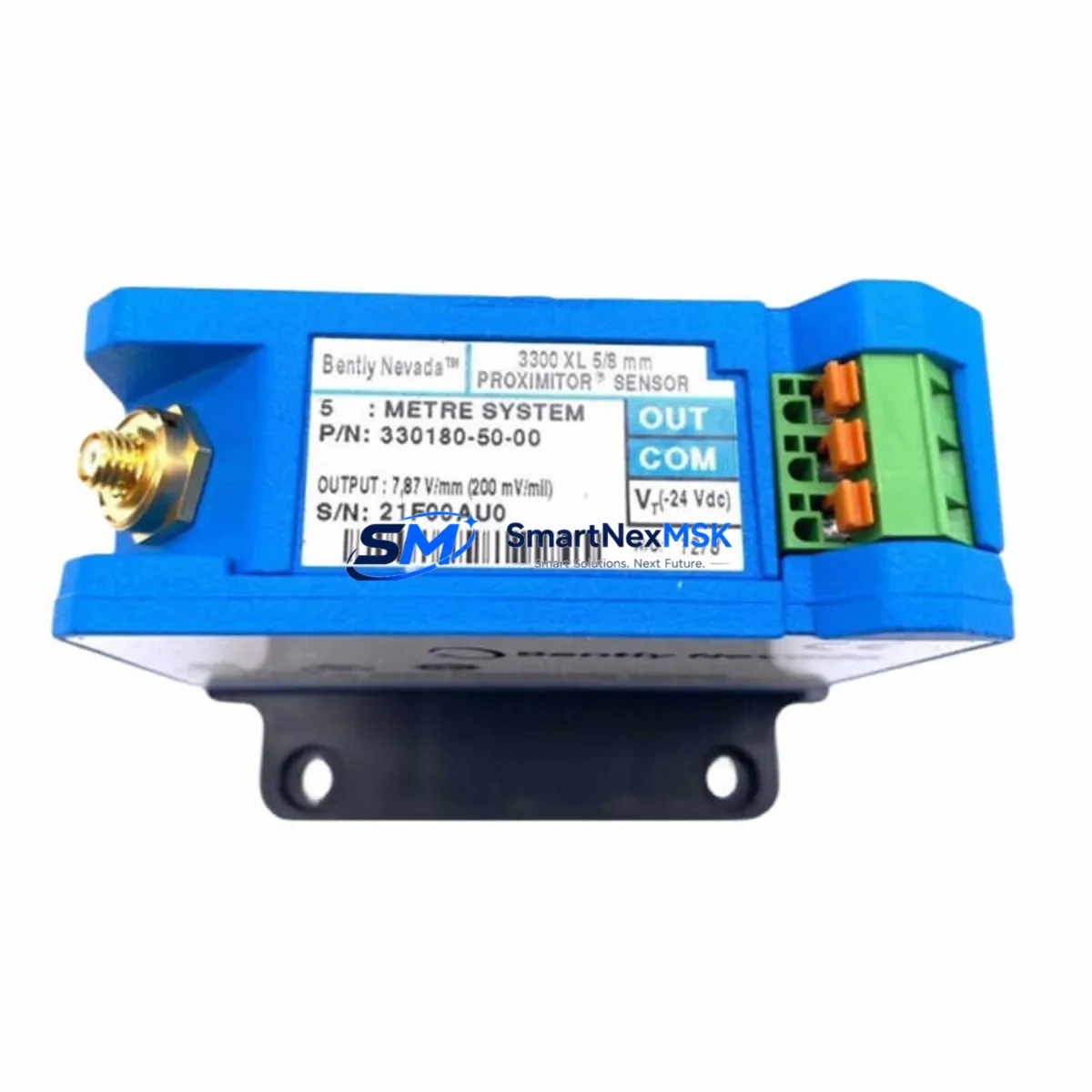
The Bently Nevada 330180-50-00 is a high-precision eddy-current Proximitor Sensor engineered for the 3300 XL vibration monitoring platform. As legacy 3300 Series installations approach end-of-service milestones, this module serves as the definitive retrofit solution — enabling plant engineers to restore full monitoring capability without replacing the entire rack infrastructure. Whether you are recovering from an unplanned sensor failure, executing a scheduled control system upgrade, or migrating from an older 3300 Series configuration, the 330180-50-00 delivers verified drop-in compatibility with minimal commissioning overhead.
Designed to interface directly with the Bently Nevada 3300 XL rack system, this Proximitor operates on the standard –24 VDC bias voltage supply and outputs a linear –24 VDC to 0 VDC signal proportional to the gap between the probe tip and the observed shaft surface. The signal chain is fully compatible with existing 3300 XL monitor cards, including the 3300/16 and 3300/20 series vibration monitors, allowing engineers to retain their existing alarm setpoints, gap voltage calibration tables, and Keyphasor reference configurations without reprogramming.
Upgrade Compatibility Table
| Parameter | 330180-50-00 Specification | Retrofit Notes |
|---|---|---|
| Supply Voltage | –24 VDC (nominal) | Compatible with standard 3300 XL power supply rails; no additional PSU required |
| Output Range | –24 VDC to 0 VDC | Direct signal compatibility with 3300/16 and 3300/20 monitor cards |
| Probe Cable Length | 5.0 m (standard) | Verify existing cable routing; extension cables available for longer runs |
| Thread / Mounting | 8 mm probe thread | Matches standard 3300 XL probe holders; no bracket modification required |
| Communication Protocol | Analog (4–20 mA / voltage) | No protocol migration required; retains existing DCS/SCADA signal mapping |
| Rack Interface | 3300 XL backplane connector | Plug-and-play with existing rack; confirm slot addressing before installation |
| Replacement Scope | Direct replacement for 330180-50-00 | Also compatible as upgrade path from 330100-series Proximitors |
| Commissioning | Gap voltage verification required | Set gap to –10.0 VDC ±0.5 VDC per 3300 XL calibration procedure |
| Warranty | 12-Month Warranty | Covers manufacturing defects; includes pre-shipment functional test report |
Retrofit Planning for Existing Automation Systems
Successful integration of the 330180-50-00 into an operating plant begins well before the module arrives on site. During the pre-retrofit engineering review, technicians should pull the existing loop drawings to confirm the three-wire hookup — power, common, and signal — matches the terminal block assignments on the 3300 XL I/O termination board. In most installations, the Proximitor connects to a dedicated termination module mounted adjacent to the monitor card slot, and the field wiring lands on numbered terminals that correspond directly to the channel address configured in the rack’s system software.
For sites running the System 1 condition monitoring platform, the channel configuration database should be exported and backed up before any hardware swap. The 330180-50-00 retains the same sensitivity coefficient (200 mV/mil or 7.87 V/mm depending on regional calibration standard), so existing System 1 transducer tables do not require modification. However, engineers should verify that the Keyphasor module — typically a 3300/55 or 3300/65 Keyphasor monitor — is correctly referenced in the channel configuration, as Keyphasor phase reference data is critical for orbit plots and 1X/2X vector analysis.
Where the retrofit scope extends beyond a single sensor, it is common to simultaneously address adjacent components. The 3300 XL power supply module, such as the 3300/15 Power Supply, should be load-tested to confirm it can support the additional sensor current draw if multiple channels are being restored. Similarly, the 3500/22M Transient Data Interface or the 3500/42M Proximitor I/O Module may be present in mixed-generation racks and should be inspected for firmware compatibility with the replacement sensor’s output characteristics.
In plants where the control architecture includes a DCS integration layer — for example, a Honeywell Experion PKS or an Emerson DeltaV system receiving vibration data via Modbus or OPC-DA — the signal mapping table in the DCS historian should be reviewed to confirm that the channel tag associated with the replaced Proximitor remains correctly bound after the hardware swap. No re-tagging is typically required for a like-for-like 330180-50-00 replacement, but the DCS operator should acknowledge and clear any sensor-fault alarms that may have latched during the outage period.
For older installations that include a 3300/25 or 3300/26 Dual Voting Logic module in the protection chain, the voting configuration should be verified post-replacement to ensure that the restored channel is correctly included in the two-out-of-three or one-out-of-two voting logic before the machine is returned to service. Bypassing the replaced channel during commissioning and then re-enabling it after gap verification is the recommended sequence to avoid spurious trips.
Downtime Control During System Migration
Minimizing unplanned downtime is the primary operational constraint in any Proximitor replacement project. The 330180-50-00 is stocked for same-day dispatch, which supports a rapid-response maintenance strategy for critical rotating equipment such as steam turbines, compressors, and pumps where continuous vibration monitoring is a safety and regulatory requirement.
The recommended replacement sequence is: (1) place the affected monitor channel in bypass mode via the 3300 XL rack front-panel bypass switch or through System 1 software; (2) de-energize the Proximitor loop at the termination module — do not disconnect at the probe end while the machine is running; (3) remove the existing 330180-50-00 or predecessor unit and install the replacement, verifying that the probe tip-to-shaft gap is within the linear range (typically 0.5 mm to 2.5 mm for an 8 mm probe); (4) power the loop and measure the output voltage at the termination module to confirm the gap voltage is within the –10.0 VDC ±0.5 VDC target; (5) remove the bypass and confirm that the System 1 or DCS display shows a valid, stable vibration reading before returning the machine to normal monitored operation.
This five-step sequence can typically be completed within 30 to 60 minutes by a qualified instrumentation technician, keeping the machine online throughout the process in most non-hazardous area installations. For ATEX or IECEx classified zones, additional isolation and hot-work permit procedures will apply and should be coordinated with the site safety team in advance.
Each 330180-50-00 unit shipped by SMARTNEXMSK undergoes a pre-shipment functional test that verifies output linearity, sensitivity coefficient, and connector integrity. A test report is included with the shipment, providing the receiving technician with a baseline reference for the as-received condition of the module.
Retrofit Support FAQ
Q: Is the 330180-50-00 a direct drop-in replacement for older 330100-series Proximitors?
A: In most 3300 XL rack configurations, yes. The 330180-50-00 uses the same –24 VDC supply, the same three-wire termination scheme, and the same 200 mV/mil sensitivity as the 330100 series. However, you should verify the probe cable length and connector type before ordering, as some early 330100-series installations used a different field connector standard.
Q: Do I need to recalibrate the System 1 database after replacing the Proximitor?
A: No recalibration of the System 1 transducer database is required for a like-for-like 330180-50-00 replacement. The sensitivity coefficient and output range are identical. You should, however, perform a gap voltage verification at the termination module after installation and confirm that the System 1 channel display shows a valid reading before removing the bypass.
Q: What wiring checks should I perform before installing the replacement module?
A: Inspect the field cable for continuity and insulation resistance, particularly if the cable has been in service for more than five years or has been routed through a high-temperature or high-vibration environment. Confirm that the terminal block screws at the 3300 XL termination module are torqued to specification and that there is no corrosion on the connector pins. A damaged field cable is a common cause of repeat sensor failures and should be replaced concurrently with the Proximitor if any degradation is found.
Q: What does the 12-month warranty cover, and is a test report included?
A: The 12-month warranty covers all manufacturing defects in materials and workmanship from the date of shipment. It does not cover damage resulting from incorrect installation, overvoltage, or mechanical impact. Every unit is functionally tested prior to shipment, and a test report confirming output linearity and sensitivity is included in the packaging. If a warranty claim is required, contact SMARTNEXMSK with the test report reference number and a description of the fault observed.
© 2026 SMARTNEXMSK. All rights reserved.
Original Source: https://smartnexmsk.com
Contact: sales@smartnexmsk.com | +86 18259474341


