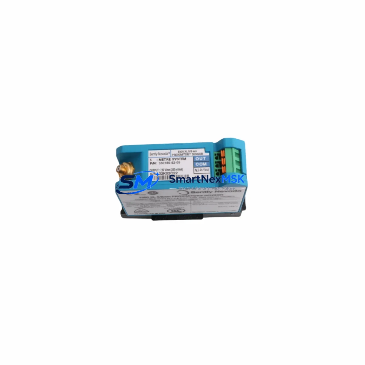
Bently Nevada 330180-52-05 Retrofit-Ready 8mm Proximity Transducer for 3300 XL Control Systems
The Bently Nevada 330180-52-05 is an 8mm proximity transducer engineered for seamless integration into existing 3300 XL Series vibration monitoring systems. As legacy Bently Nevada installations age and original components approach end-of-life, the 330180-52-05 provides a verified, wiring-compatible retrofit solution that preserves your existing cable infrastructure, signal conditioning chain, and machinery protection logic — without requiring a full system overhaul.
This transducer is designed for industrial environments where continuous uptime is critical. Whether you are replacing a failed sensor on a rotating machine, upgrading a control cabinet, or executing a planned maintenance retrofit, the 330180-52-05 delivers the measurement accuracy and mechanical compatibility required by the 3300 XL platform. It is suitable for use in turbines, compressors, pumps, gearboxes, and other rotating equipment monitored under API 670 machinery protection standards.
Upgrade Compatibility Table
| Parameter | Detail |
|---|---|
| SKU / Part Number | 330180-52-05 |
| Brand | Bently Nevada |
| Series Compatibility | 3300 XL Series Vibration Monitoring System |
| Transducer Diameter | 8mm |
| Signal Output | -18 VDC nominal (standard Bently Nevada proximitor output) |
| Cable / Connector Interface | Compatible with standard 3300 XL extension cables and proximitor drivers |
| Mounting Thread | M10 x 1 (standard 8mm probe thread) |
| Installation Requirement | Requires matching extension cable (e.g. 330130 series) and proximitor (e.g. 3300 XL 8mm Proximitor) |
| Communication Compatibility | Analog 4–20 mA / voltage output via 3300 XL monitor rack |
| Replacement Recommendation | Direct drop-in for failed or end-of-life 330180-52-05 units in 3300 XL installations |
| Commissioning Notes | Verify gap voltage, scale factor, and proximitor driver calibration after installation |
| Warranty | 12-Month Warranty — covers manufacturing defects and functional failure under normal operating conditions |
Retrofit Planning for Existing Automation Systems
Successful retrofit of the 330180-52-05 into an operational plant requires systematic pre-installation planning. Before removing the existing transducer, engineers should document the current gap voltage reading at the proximitor driver — typically a 3300 XL 8mm Proximitor module — and confirm that the replacement probe achieves the same nominal gap within the linear range specified in the calibration datasheet.
The extension cable connecting the probe to the proximitor must be verified for length and impedance matching. Standard 330130 series extension cables are commonly used in 3300 XL installations, and their condition should be inspected during any probe replacement. If the cable shows signs of insulation damage or connector corrosion, replacement with a new 330130-series cable is recommended before commissioning the new transducer.
At the monitor rack level, the 3300 XL monitor card — such as the 3300/16 or 3300/20 series vibration monitor — must be confirmed to be in a healthy state before the new probe is energized. Rack backplane connections and I/O terminal assignments should be verified against the original loop drawing. If the installation includes a 3500 Series rack as part of a parallel or upgraded monitoring architecture, ensure that the channel configuration in the 3500/42M or 3500/40M monitor card reflects the correct transducer sensitivity and gap parameters.
For plants that have migrated or are migrating from 3300 XL to 3500 Series machinery protection, the 330180-52-05 remains compatible with 3500 Series proximitor drivers when used with the appropriate 3500 XL 8mm transducer system configuration. This makes it a practical interim solution during phased upgrades where not all channels have been converted simultaneously.
HMI screens connected to the DCS or SCADA system — whether running on a GE Mark VIe, Emerson DeltaV, or Honeywell Experion platform — should be reviewed to confirm that vibration trend displays, alarm setpoints, and trip thresholds remain correctly mapped after the transducer swap. Any changes to the proximitor output scaling must be reflected in the HMI tag configuration to avoid false alarms or missed trips.
Where the 3300 XL system interfaces with a Modbus RTU or FOUNDATION Fieldbus communication link to the plant DCS, the communication link should be verified as live and error-free before and after the retrofit. If the installation includes a 3300/55 communication gateway or a 3500/92 communication module, confirm that the module firmware is current and that the channel mapping has not been disrupted by the maintenance activity.
Power supply integrity is a critical pre-check. The 3300 XL system typically operates on a -24 VDC supply rail. Confirm that the power supply module — often a dedicated 3300 XL power supply or a shared rack supply — is delivering stable voltage within specification before energizing the new transducer. A marginal power supply can cause erratic gap readings and false vibration alarms that complicate commissioning.
Downtime Control During System Migration
Minimizing unplanned downtime during a transducer retrofit requires a structured hot-swap or planned-outage strategy. For machinery that cannot be taken offline, a bypass procedure using the 3300 XL monitor’s bypass/inhibit function allows maintenance personnel to temporarily suppress the vibration channel alarm while the probe is being replaced, without disabling the overall machinery protection system. This preserves control continuity on adjacent channels and prevents nuisance trips during the swap.
Before initiating the bypass, the original program logic in the associated safety PLC or DCS controller — whether a Rockwell Automation ControlLogix, Siemens S7-400, or ABB AC800M — should be documented and backed up. Any interlock that references the vibration channel being serviced must be identified and temporarily managed through the appropriate bypass or override procedure defined in the plant’s management of change (MOC) protocol.
Once the 330180-52-05 is installed and the gap voltage is confirmed within the linear range, the bypass should be released and the channel monitored for a minimum stabilization period — typically 15 to 30 minutes — before the machinery is returned to full load. During this period, vibration trend data should be compared against the historical baseline to confirm that the new transducer is performing consistently with the previous measurement. Any deviation in the 1X or 2X vibration component should be investigated before clearing the work order.
All retrofit activities should be documented in the plant’s maintenance management system (CMMS), including the as-found gap voltage, as-left gap voltage, cable condition, and any deviations from the standard installation procedure. This documentation supports future troubleshooting and provides traceability for the 12-month warranty period.
Retrofit Support FAQ
Q: Is the 330180-52-05 a direct replacement for the original Bently Nevada part of the same number?
A: Yes. The 330180-52-05 is supplied to the original Bently Nevada specification and is a direct functional replacement. It is compatible with the 3300 XL 8mm proximitor driver and standard 330130 series extension cables. No modification to the existing wiring or monitor configuration is required for a like-for-like swap.
Q: What commissioning checks are required after installation?
A: After installation, verify the probe gap voltage at the proximitor driver output — the nominal gap for an 8mm probe is typically -10 VDC at 1.0 mm gap. Confirm the scale factor matches the monitor card configuration. Check that the vibration channel is reading within the expected baseline range and that no alarms are active before releasing the bypass and returning the machine to service.
Q: Can this transducer be used with a 3500 Series monitor rack?
A: The 330180-52-05 is designed for the 3300 XL platform. Compatibility with 3500 Series monitor cards depends on the specific proximitor driver and channel configuration. In many phased upgrade scenarios, the probe can be used with a 3500 XL 8mm transducer system configuration. Confirm with your system integrator or refer to the 3500 Series installation manual for channel-specific compatibility requirements.
Q: What does the 12-month warranty cover?
A: The 12-month warranty covers manufacturing defects and functional failure under normal operating and installation conditions. Each unit undergoes pre-shipment functional testing to verify output linearity, gap response, and connector integrity. Warranty claims require documentation of the installation conditions and the as-found fault description. Contact sales@smartnexmsk.com for warranty support.
© 2026 SMARTNEXMSK. All rights reserved.
Original Source: https://smartnexmsk.com
Contact: sales@smartnexmsk.com | +86 18259474341


