Bently Nevada 330180-91-05 Maintenance-Ready Spare for 3300 XL Automation
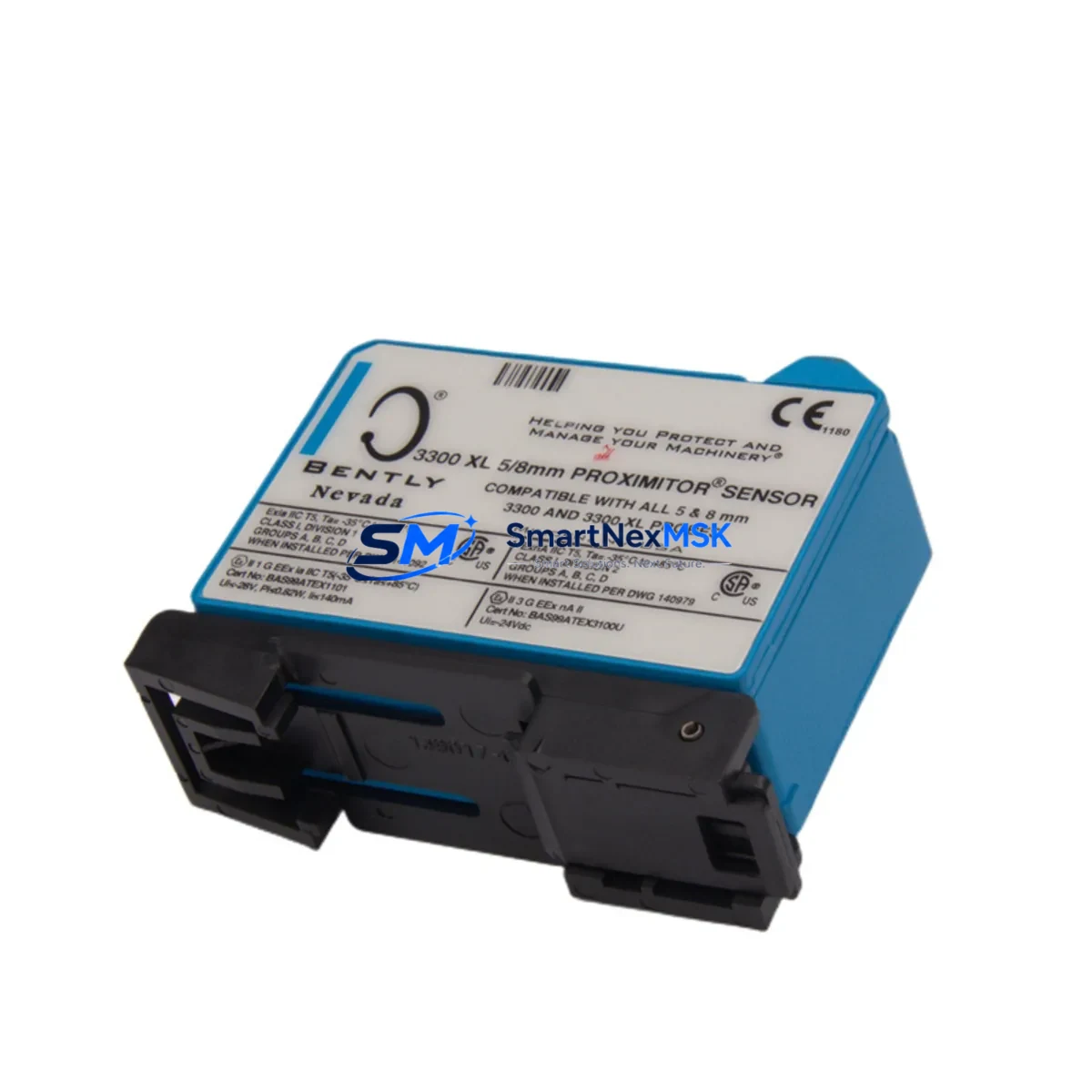
The Bently Nevada 330180-91-05 is an original eddy current proximitor sensor engineered for the 3300 XL Series continuous vibration monitoring platform. In industrial facilities running rotating machinery — turbines, compressors, pumps, and gearboxes — this proximitor converts the raw output of an eddy current probe into a conditioned DC voltage signal proportional to the gap between the probe tip and the target shaft. Accurate, stable, and interference-resistant, the 330180-91-05 is a critical component in any predictive maintenance programme where unplanned downtime carries significant operational and financial risk.
For maintenance engineers managing ageing DCS or machinery protection systems, sourcing a verified original spare is the first line of defence against false trips, missed alarms, and catastrophic bearing failures. This unit ships tested, serialised, and backed by a 12-month warranty, giving procurement teams the confidence to stock it as a long-cycle spare without concern for shelf-life degradation.
Spare Maintenance Table
| Parameter | Specification |
|---|---|
| SKU / Part Number | 330180-91-05 |
| Brand | Bently Nevada |
| Series | 3300 XL Vibration Monitoring System |
| Product Type | Eddy Current Proximitor Sensor |
| Output Signal | DC voltage proportional to probe gap (–24 VDC system) |
| Compatible Probes | Bently Nevada 3300 XL 8 mm eddy current probe assemblies |
| Supply Voltage | –24 VDC (nominal) |
| Operating Temperature | –35 °C to +85 °C |
| Enclosure / Housing | DIN-rail or panel-mount compatible, IP-rated per installation |
| Origin | United States |
| Application Environment | Turbines, compressors, pumps, gearboxes, rotating machinery |
| Maintenance Recommendation | Replace at first sign of signal drift, noise, or gap alarm deviation; inspect every planned outage cycle |
| Warranty | 12 Months |
| Condition | Original, new or fully tested surplus |
| Shipping | Tested before dispatch; global express available |
Maintenance Planning for Continuous Operation
When a 330180-91-05 proximitor sensor is flagged for replacement during a planned outage or emergency shutdown, experienced maintenance engineers know that the sensor itself is rarely the only component that warrants attention. A systematic inspection of the entire vibration monitoring loop — and the broader control cabinet — is essential to restore full system integrity and prevent repeat failures.
Begin with the eddy current probe assembly (typically a Bently Nevada 3300 XL 8 mm probe, part of the 330104 or 330130 series) and its extension cable. Cable insulation breakdown or connector corrosion is a common root cause of proximitor signal anomalies that are misdiagnosed as sensor failure. Inspect the full cable run from probe tip to proximitor input, paying particular attention to any conduit entry points or areas subject to vibration fatigue.
Next, verify the –24 VDC power supply module feeding the proximitor rack. Voltage sag or ripple on the supply rail will directly corrupt gap measurements and trigger nuisance alarms. If the facility runs a Bently Nevada 3500 Series rack alongside legacy 3300 XL hardware, confirm that power distribution is correctly segregated and that the 3500/15 Power Supply or equivalent is within specification.
Within the control cabinet, inspect the terminal blocks and field wiring terminations on the proximitor output circuit. Loose or oxidised terminals introduce resistance that shifts the DC output level and can cause the monitoring system to report false high-vibration conditions. While the cabinet is open, check the condition of the I/O signal conditioning modules that interface the proximitor output to the DCS or safety system — these modules age independently of the sensor and are frequently overlooked during spare-parts planning.
For facilities using a Bently Nevada 3500/42M Proximitor/Seismic Monitor or similar rack-mounted monitor card, confirm that the monitor’s gap, direct, and 1X/2X alarm setpoints are correctly configured for the replacement sensor’s sensitivity (mV/mil or mV/µm). A sensor swap without setpoint verification is a common source of post-maintenance alarm floods.
Procurement engineers building a comprehensive spare-parts kit around the 330180-91-05 should also consider stocking the 3300 XL proximitor junction box, field barrier modules for hazardous-area installations, and a quantity of M12 connector assemblies for rapid field replacement. Where the machinery protection system interfaces with a Modbus or FOUNDATION Fieldbus communication module, ensure that module firmware is current and that a tested spare is available — communication faults during a restart sequence can delay return-to-service by hours.
Finally, if the plant operates legacy rotating machinery where the 3300 XL system is approaching end-of-support, consider a parallel stock of signal isolators to bridge the proximitor output into a modern DCS input card. This approach extends the useful life of the existing sensor infrastructure without requiring a full system upgrade, protecting capital budgets while maintaining measurement integrity.
Site Replacement Workflow
Step 1 — Isolation and permit: Obtain a valid permit-to-work and isolate the –24 VDC supply to the proximitor rack before disconnecting any field wiring. Confirm isolation with a calibrated multimeter at the terminal block.
Step 2 — Document existing gap voltage: Before removal, record the current gap voltage displayed on the monitor or DCS faceplate. This baseline value confirms the probe-to-shaft gap and allows rapid verification after reinstallation.
Step 3 — Remove and label: Disconnect the extension cable from the proximitor input connector. Label the cable with the channel number and tag reference. Remove the 330180-91-05 from its mounting position, noting any orientation or torque requirements.
Step 4 — Inspect and clean: Inspect the mounting surface, connector pins, and cable termination for corrosion, mechanical damage, or contamination. Clean with an appropriate contact cleaner before fitting the replacement unit.
Step 5 — Install replacement: Mount the new 330180-91-05, reconnect the extension cable, and restore the –24 VDC supply. Allow a 30-second warm-up period before reading the gap voltage.
Step 6 — Verify gap and alarm setpoints: Confirm the gap voltage matches the pre-removal baseline (±acceptable tolerance per site procedure). Verify that direct, 1X, and alarm setpoints on the monitor card are appropriate for the installed probe sensitivity. Perform a functional test by simulating a gap change if site procedures permit.
Step 7 — Return to service and document: Clear any latched alarms, confirm healthy status on the DCS or machinery protection HMI, and update the maintenance management system with the replacement date, new serial number, and post-installation gap reading. Retain the removed unit for failure analysis if required.
This workflow minimises return-to-service time, maintains system compatibility, and creates a traceable maintenance record — all critical requirements for facilities operating under ISO 55000 asset management or API 670 machinery protection standards.
Spare Parts Support FAQ
Q1: What is the expected service life of the 330180-91-05, and when should I plan a proactive replacement?
Bently Nevada proximitor sensors are designed for long service life under normal operating conditions, but signal drift, connector degradation, and thermal cycling in high-temperature environments can reduce effective life to 5–10 years in demanding applications. Best practice is to schedule proactive replacement during every major planned outage if the unit has been in service for more than seven years, or immediately upon any confirmed signal anomaly that cannot be attributed to the probe or cable.
Q2: How do I confirm compatibility between the 330180-91-05 and my existing probe and extension cable?
The 330180-91-05 is designed for use with Bently Nevada 3300 XL 8 mm eddy current probe systems. Compatibility is determined by the probe series, cable length, and system sensitivity (mV/mil). Verify the probe part number and cable length against the Bently Nevada system configuration record for your machine. If documentation is unavailable, the gap voltage at a known mechanical clearance can be used to back-calculate sensitivity and confirm compatibility before the unit is placed in service.
Q3: What pre-shipment testing is performed, and what does the 12-month warranty cover?
Every 330180-91-05 unit is functionally tested prior to dispatch to verify output linearity, supply current draw, and connector integrity. The 12-month warranty covers defects in materials and workmanship under normal operating conditions. Units returned within the warranty period are inspected, repaired, or replaced at no charge. Warranty claims require the original order reference and a brief description of the observed fault.
Q4: Can the 330180-91-05 be used as a direct replacement for older 3300 Series (non-XL) proximitors?
The 3300 XL series introduced revised sensitivity specifications and connector configurations compared to the original 3300 series. Direct interchangeability depends on the specific probe assembly and monitor card in use. Before substituting a 330180-91-05 for a non-XL proximitor, confirm the monitor card’s input range and the probe sensitivity specification. In most cases, a full 3300 XL probe-cable-proximitor set replacement is the safest approach to ensure system calibration integrity.
© 2026 SMARTNEXMSK. All rights reserved.
Original Source: https://smartnexmsk.com
Contact: sales@smartnexmsk.com | +86 18259474341


