Bently Nevada 330180-X0-05 Maintenance-Ready Spare for 3300 XL Automation
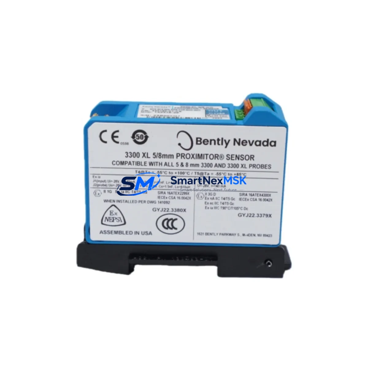
The Bently Nevada 330180-X0-05 (MOD:145193-01) is an original proximitor sensor engineered for continuous shaft vibration and position monitoring within the 3300 XL Series condition monitoring system. For maintenance engineers managing rotating machinery — turbines, compressors, pumps, and gearboxes — this proximitor is a critical front-line component. Unplanned failure of this unit directly triggers vibration alarm trips, forcing unscheduled shutdowns and costly production losses. Stocking a verified replacement ensures rapid restoration of monitoring integrity and minimizes mean time to repair (MTTR).
This unit is sourced as an original spare, fully tested prior to dispatch, and backed by a 12-month warranty. It is suitable for direct drop-in replacement in existing 3300 XL panel installations without requiring reconfiguration of the monitoring rack or recalibration of the overall system chain — provided the eddy-current probe and extension cable specifications are matched correctly.
Spare Maintenance Table
| Parameter | Specification |
|---|---|
| Part Number | 330180-X0-05 |
| Modification | MOD:145193-01 |
| Brand | Bently Nevada |
| Series | 3300 XL Condition Monitoring System |
| Product Type | Proximitor Sensor / Eddy-Current Signal Conditioner |
| Output Signal | –24 VDC nominal (standard Bently Nevada scale factor) |
| Supply Voltage | –24 VDC (from 3300 XL rack power supply) |
| Compatible Probes | 3300 XL 8mm Proximity Probes (e.g. 330103, 330104 series) |
| Compatible Extension Cables | 3300 XL Extension Cables (e.g. 330130 series) |
| Measurement Application | Radial vibration, axial position, differential expansion |
| Installation Environment | Industrial control cabinet, DCS/PLC panel, machinery protection rack |
| Mounting | DIN rail / rack-mount per 3300 XL system chassis |
| Origin | USA |
| Condition | Original spare, tested before dispatch |
| Warranty | 12 Months |
| Lead Time | In stock — ships within 1–3 business days |
Maintenance Planning for Continuous Operation
When replacing the 330180-X0-05 proximitor during a planned or emergency maintenance event, a disciplined inspection of the surrounding signal chain and power infrastructure is essential to prevent repeat failures and ensure the monitoring system returns to full specification.
Begin by verifying the 3300 XL rack power supply module — the proximitor operates on a regulated –24 VDC rail, and any ripple or voltage sag from an aging power supply will degrade output linearity and trigger false alarms. Inspect the 330103 or 330104 series 8mm proximity probe at the machine end: check the probe tip for physical damage, contamination, or gap drift beyond the linear range. The 330130 series extension cable connecting the probe to the proximitor must also be inspected for insulation breakdown, connector corrosion, and continuity — a degraded cable is a common root cause of proximitor replacement that is overlooked.
At the rack level, review the 3300 XL monitor module (such as the 3300/16 or 3300/20 series) paired with this proximitor channel. Confirm that the monitor’s OK relay output and alarm setpoints are functioning correctly after the proximitor swap. If the installation includes a 3300 XL keyphasor module, verify its signal integrity as well — phase reference errors can mask true vibration readings post-replacement.
For cabinet-level inspection, check the terminal blocks and field wiring connecting the proximitor to the monitor. Loose terminations on the signal and shield conductors are a frequent source of noise injection. If the system feeds into a DCS I/O card or safety PLC analog input module, confirm that the 4–20 mA or voltage output from the monitor is within the expected engineering unit range after the new proximitor is installed. Where signal isolators or barriers are used between the 3300 XL output and the DCS, inspect these for drift or failure — they are often overlooked during proximitor-focused maintenance events.
Finally, if the plant operates an HMI or SCADA display tied to this vibration channel, perform a live signal walk-through after replacement to confirm that trend data, alarm annunciation, and historian logging are all functioning correctly before returning the machine to service.
Site Replacement Workflow
Step 1 — Isolation: De-energize the 3300 XL rack channel or isolate the affected monitor slot per your site LOTO procedure. Do not remove the proximitor under live power without confirming the monitor’s bypass/inhibit function is active to prevent spurious trips.
Step 2 — Documentation: Record the existing gap voltage (typically –10 VDC ±0.5 V for standard 8mm probes at nominal gap) before removal. This baseline is required to verify correct reinstallation of the replacement unit.
Step 3 — Removal and inspection: Disconnect the extension cable connector and remove the 330180-X0-05 from the rack. Inspect the connector pins and the rack slot contacts for oxidation or mechanical damage.
Step 4 — Installation: Insert the replacement 330180-X0-05 (MOD:145193-01) into the rack slot. Reconnect the extension cable. Restore power and allow the proximitor a brief warm-up period (typically 2–5 minutes) before reading the gap voltage.
Step 5 — Verification: Confirm the gap voltage matches the pre-removal baseline within ±0.2 V. Check the monitor OK LED and confirm the channel is in the OK state. Clear any latched alarms and verify the vibration reading is within the expected baseline range for the machine at its normal operating speed.
Step 6 — Return to service: Remove the monitor inhibit, restore the channel to normal protection mode, and document the replacement in the plant maintenance management system (CMMS). Update the spare parts inventory to trigger reorder of a replacement unit for the next event.
Spare Parts Support FAQ
Q1: Is the 330180-X0-05 MOD:145193-01 a direct replacement for earlier MOD revisions?
In most 3300 XL installations, MOD revisions represent manufacturing or component updates that maintain full functional and dimensional compatibility. However, always cross-reference the system documentation or contact our technical team to confirm compatibility with your specific rack revision before installation.
Q2: How is the unit tested before dispatch?
Each 330180-X0-05 unit undergoes functional verification including output voltage check, OK relay operation, and signal linearity confirmation against a reference probe and cable set. A test report is available upon request. Units are dispatched with protective packaging to prevent ESD and mechanical damage in transit.
Q3: What is covered under the 12-month warranty?
The 12-month warranty covers manufacturing defects and functional failures under normal operating conditions. It does not cover damage resulting from incorrect installation, overvoltage, or physical mishandling. Warranty claims are processed with return of the defective unit and a brief fault description.
Q4: Can you support long-term or blanket spare parts orders for this SKU?
Yes. For plants with multiple 3300 XL systems or high-criticality rotating machinery, we support scheduled blanket orders and consignment stock arrangements. Contact our team to discuss volume pricing, lead time commitments, and multi-site supply agreements.
© 2026 SMARTNEXMSK. All rights reserved.
Original Source: https://smartnexmsk.com
Contact: sales@smartnexmsk.com | +86 18259474341


