Bently Nevada 330194-00-06-05-00 Retrofit-Ready Proximity Probe for 3300 XL Control Systems
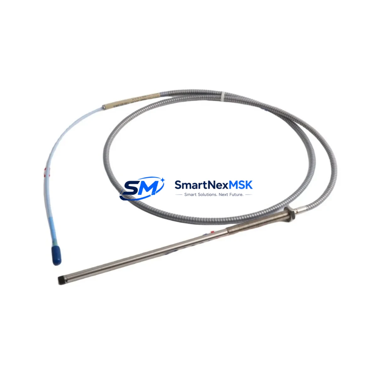
The Bently Nevada 330194-00-06-05-00 is a high-precision eddy-current proximity probe engineered for vibration and position monitoring in rotating machinery. Designed as a direct retrofit replacement within the Bently Nevada 3300 XL Extended Temperature Range (ETR) platform, this probe supports smooth migration from legacy 3300 Series installations to modernized condition monitoring architectures — without requiring changes to existing cabling, conduit runs, or junction box terminations.
Industrial facilities operating aging turbomachinery protection systems frequently encounter discontinued spare parts, extended lead times, and compatibility gaps when sourcing original components. The 330194-00-06-05-00 addresses these challenges directly: it maintains the same 5-metre cable length, standard 8 mm probe tip diameter, and TNC connector interface as the original factory specification, enabling drop-in installation during planned outages or emergency maintenance windows.
Upgrade Compatibility Table
| Parameter | 330194-00-06-05-00 (This Unit) | Legacy 3300 Series Equivalent |
|---|---|---|
| Probe Tip Diameter | 8 mm | 8 mm |
| Cable Length | 5 m (standard) | 5 m |
| Connector Type | TNC | TNC |
| Operating Temperature | -35°C to +177°C (ETR) | -18°C to +121°C (standard) |
| Driver Compatibility | 3300 XL 8 mm Driver (330180 series) | 3300 8 mm Driver |
| Mounting Thread | M10 × 1.0 | M10 × 1.0 |
| Installation Requirement | No bracket modification required | Standard bracket |
| Communication / Signal | Analogue voltage output (–24 VDC bias) | Analogue voltage output |
| Replacement Recommendation | Direct drop-in for 330104, 330130 series probes | — |
| Commissioning Note | Re-verify gap voltage (–10.0 VDC ± 0.5 V at nominal gap) | Same procedure |
| Warranty | 12 Months | OEM warranty (varies) |
Retrofit Planning for Existing Automation Systems
Replacing proximity probes in an operating plant requires careful coordination across multiple system layers. Before removing the legacy probe, technicians should document the existing gap voltage reading at the Bently Nevada 3300 XL 8 mm Driver (typically a 330180-X1-00 or 330180-X1-05 driver module) and record the OK relay status on the associated 3300/16-24-05-02-00 monitor card. This baseline ensures that post-installation verification can confirm the replacement probe is operating within the original calibration envelope.
Wiring continuity is the first physical checkpoint. The 330194-00-06-05-00 uses a standard coaxial cable terminated with a TNC connector, which mates directly to the 3300 XL proximitor/driver without adapters. Confirm that the existing conduit and cable tray routing does not introduce sharp bends exceeding the probe cable’s minimum bend radius. Where cable runs exceed 5 metres, an extension cable (330130-080-00-00 series) may be required to bridge the distance to the driver enclosure — verify total system cable length against the driver’s calibrated range before finalising the installation.
At the rack level, the 3300 XL monitor system typically resides in a 3300/05 or 3300/10 rack housing multiple monitor cards, a 3300/15 power supply module, and a 3300/46 or 3300/55 communication gateway for Modbus RTU or Ethernet/IP integration with the plant DCS. When retrofitting probes during a broader system upgrade — for example, migrating from a legacy Bently Nevada 3500 Series rack to a 3300 XL architecture — it is essential to re-map channel addresses in the System 1 condition monitoring software and update any associated HMI display pages that reference the original probe tag names.
I/O expansion during a control cabinet upgrade may also involve adding 3300/25 or 3300/20 monitor modules to accommodate additional measurement points on upgraded turbine trains. In these scenarios, the 330194-00-06-05-00 probe can be deployed on new measurement planes — such as thrust position or differential expansion — without requiring a separate probe family, simplifying spare parts inventory management across the facility.
For plants integrating condition monitoring data into a Rockwell Automation ControlLogix or Siemens S7-300/S7-400 PLC via the 3300 XL gateway, confirm that the Modbus register map or EtherNet/IP tag table reflects the new channel assignments before re-energising the monitor rack. Failure to update the PLC program’s analogue input scaling blocks can result in false alarm conditions or missed trip signals during the post-installation functional test.
Downtime Control During System Migration
Minimising unplanned downtime during a proximity probe replacement begins with pre-staging all components before the maintenance window opens. Verify that the replacement 330194-00-06-05-00 probe, the associated driver module, and any required extension cables are on-site and bench-tested before the machine is taken offline. A pre-installation continuity check — measuring coaxial cable resistance and confirming TNC connector integrity — eliminates the risk of discovering a transit-damaged component after the machine is already shut down.
Where the plant schedule permits only a short outage window, consider a parallel-installation approach: mount the new probe in an adjacent bracket position, route its cable to a spare driver channel, and verify gap voltage and OK status before transferring the monitor channel assignment. This technique preserves the original probe’s signal path until the replacement is confirmed operational, reducing the risk of an extended outage caused by a calibration discrepancy.
After physical installation, the commissioning sequence should follow the Bently Nevada standard gap-setting procedure: adjust the probe-to-target gap to achieve a –10.0 VDC ± 0.5 V output at the driver, confirm the OK relay energises, and perform a static calibration check across the full measurement range. Document the final gap voltage, driver output voltage, and OK relay status in the plant maintenance management system before returning the machine to service. All units supplied by SMARTNEXMSK are pre-tested prior to shipment and covered by a 12-month warranty against manufacturing defects.
Retrofit Support FAQ
Q1: Is the 330194-00-06-05-00 a direct replacement for the 330104-00-06-05-00?
Yes. The 330194 series is the ETR (Extended Temperature Range) successor to the 330104 series. Both use the same 8 mm probe tip, M10 × 1.0 mounting thread, TNC connector, and 5 m cable length. The primary difference is the extended operating temperature range of the 330194, making it suitable for high-temperature bearing housings and steam turbine applications where the 330104 may have been marginal.
Q2: Do I need to recalibrate the 3300 XL driver after installing this probe?
A gap voltage verification is always recommended after any probe replacement, even for direct drop-in substitutions. Set the probe-to-target gap to the nominal value specified in your machine’s vibration monitoring datasheet (typically 1.0–1.5 mm for 8 mm probes), then confirm the driver output reads –10.0 VDC ± 0.5 V. If the reading falls outside this range, adjust the gap accordingly. Full recalibration of the driver module is not required unless the driver itself has been replaced.
Q3: Can this probe be used with a Bently Nevada 3500/42M monitor?
The 330194-00-06-05-00 is calibrated for use with the 3300 XL driver family. While the physical connector and cable are compatible with 3500 Series proximitor inputs, the system sensitivity and scale factor must be verified against the 3500/42M monitor’s configuration. Consult the 3500/42M datasheet and confirm that the selected probe/driver combination matches the monitor’s expected input range before deploying in a 3500 Series rack.
Q4: What does the 12-month warranty cover, and how is it claimed?
All 330194-00-06-05-00 units supplied by SMARTNEXMSK carry a 12-month warranty covering manufacturing defects, premature failure under normal operating conditions, and out-of-specification performance at the time of delivery. Warranty claims are initiated by contacting our technical support team with the order reference, installation date, and a description of the observed fault. Units confirmed defective will be replaced or credited at our discretion. Physical damage resulting from incorrect installation, over-range mechanical shock, or chemical exposure is excluded from warranty coverage.
© 2026 SMARTNEXMSK. All rights reserved.
Original Source: https://smartnexmsk.com
Contact: sales@smartnexmsk.com | +86 18259474341


