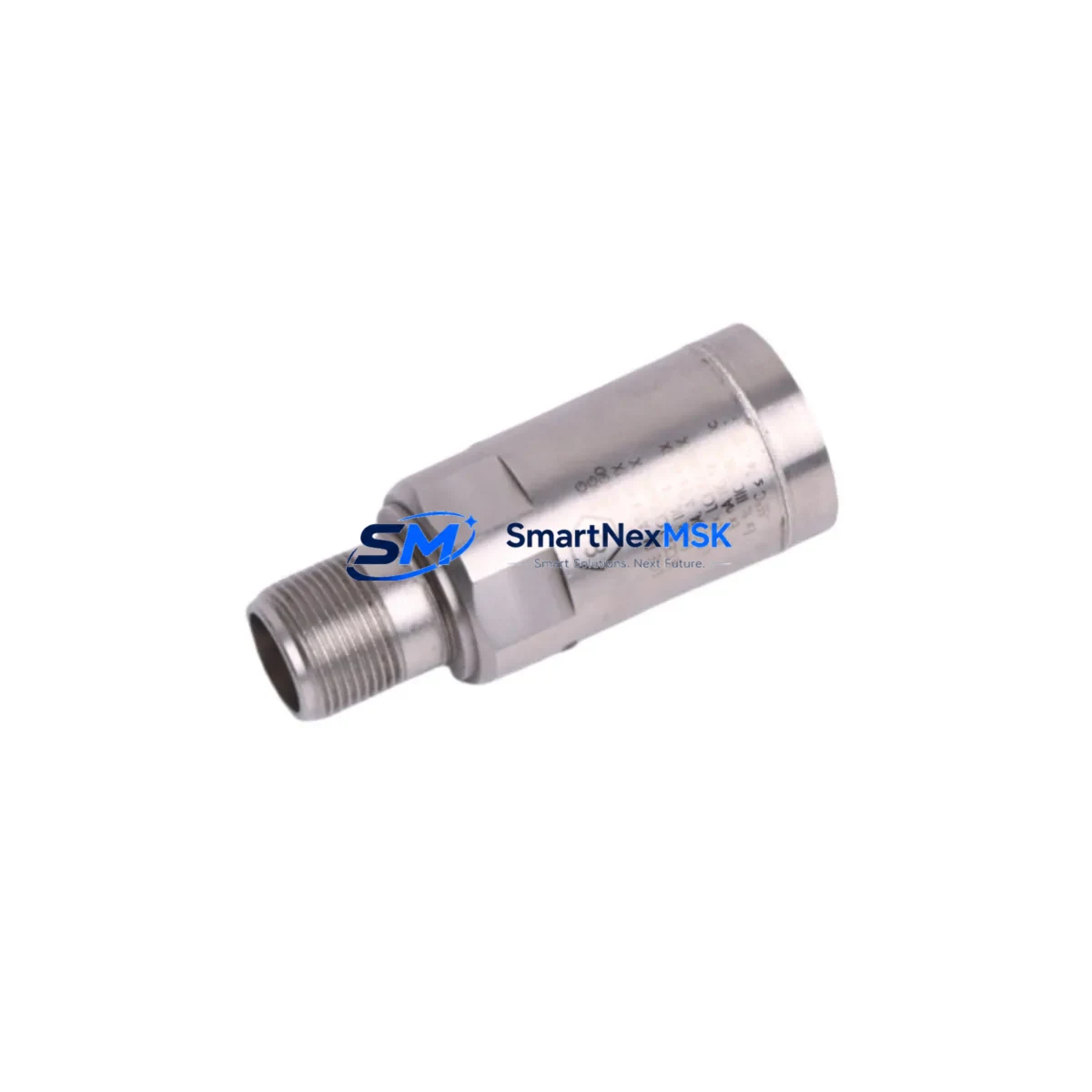
Bently Nevada 330500-03-00 Spare for 3300 Series Automation
The Bently Nevada 330500-03-00 is an original seismic velocity sensor engineered for the 3300 Series Proximitor/Seismic monitoring system — one of the most widely deployed vibration and machinery protection platforms in rotating equipment facilities worldwide. Whether you are managing a planned turnaround, responding to an unplanned trip, or building a critical-path spare parts inventory, the 330500-03-00 represents a direct, drop-in replacement that eliminates compatibility risk and accelerates return-to-service timelines.
For maintenance engineers and reliability teams operating gas turbines, steam turbines, compressors, pumps, and gearboxes, the seismic velocity channel is a first-line indicator of structural vibration and bearing health. A failed or degraded 330500-03-00 sensor can cause nuisance trips, masked fault conditions, or — in worst-case scenarios — undetected machinery damage. Stocking a verified original spare is not optional in high-availability plants; it is a fundamental element of any machinery protection strategy.
Each unit supplied by SMARTNEXMSK is sourced from authorized channels, individually tested prior to dispatch, and covered by a 12-month warranty. We support industrial buyers who require documentation, traceability, and rapid fulfillment — not just a part number match.
Spare Maintenance Table
| SKU / Part Number | 330500-03-00 |
| Brand | Bently Nevada |
| Series | 3300 Proximitor / Seismic Series |
| Product Type | Seismic Velocity Sensor |
| Sensor Output | Velocity (mV/mm/s or mV/in/s, per system configuration) |
| Mounting | Stud-mount, compatible with standard 3300 Series mounting hardware |
| Operating Temperature | -40°C to +121°C (typical industrial range) |
| Compatibility | Bently Nevada 3300 Series monitors, 3500 Series rack (with appropriate I/O module), legacy Proximitor systems |
| Application Environment | Rotating machinery: gas turbines, steam turbines, centrifugal compressors, pumps, gearboxes |
| Origin | USA |
| Condition | Original spare — new or recertified, individually tested before shipment |
| Warranty | 12 months from date of shipment |
| Lead Time | In-stock units ship within 1–3 business days |
| Documentation | Test report, datasheet, and traceability certificate available on request |
Maintenance Planning for Continuous Operation
When a 330500-03-00 seismic velocity sensor is flagged for replacement during a routine control cabinet inspection or a machinery protection audit, experienced maintenance engineers know that the sensor itself is rarely the only component that warrants attention. A comprehensive replacement workflow should include verification of the associated 3300/16 Proximitor monitor module and its I/O termination board, since connector wear and signal drift at the module level can mimic sensor failure and lead to repeat callouts.
The 3300/55 Dual Velocity Monitor or equivalent rack-mounted monitor card should be bench-tested or swapped with a known-good spare during the same maintenance window. Signal integrity from the 330500-03-00 depends on clean, shielded cabling — inspect the 330130 extension cable and 330180 armored cable assemblies for insulation breakdown, connector corrosion, or mechanical damage caused by vibration fatigue over long service cycles.
At the power supply level, confirm that the 3300/20 Power Supply module is delivering stable ±24 VDC to the monitor rack. Voltage sag or ripple at the rack bus is a common root cause of intermittent sensor alarms that are incorrectly attributed to the transducer. If the facility runs a 3500 Series rack alongside legacy 3300 equipment, verify that the 3500/42M Proximitor/Seismic Monitor I/O module is correctly configured for the velocity input range of the replacement sensor.
For plants using a System 1 Evolution or Orbit 60 Series condition monitoring platform, recalibrate the channel after sensor replacement and confirm that alarm setpoints, full-scale ranges, and OK relay logic are correctly restored in the software. Relay output modules — particularly the 3300/32 Relay Module — should be tested for contact integrity if the sensor replacement follows a machinery trip event, as relay contacts can be damaged by repeated high-current switching during emergency shutdowns.
Terminal blocks and field wiring terminations in the junction box should be inspected and torqued to specification. Loose terminations at the 3300 Series field wiring termination board are a frequent source of noise injection that degrades sensor signal quality. Where signal isolation is required between the machinery protection system and the DCS historian, a signal isolator/conditioner (such as a DIN-rail mounted 4–20 mA isolator) should be verified for correct loop impedance and isolation voltage.
Site Replacement Workflow
Step 1 — Pre-replacement verification: Confirm the replacement 330500-03-00 part number, revision, and cable length match the installed unit. Cross-reference the Bently Nevada 3300 Series installation manual for mounting torque and cable routing requirements. If the existing sensor has been in service for more than 5 years, consider replacing the extension cable assembly at the same time to avoid a repeat outage.
Step 2 — Safe isolation: Follow site lock-out/tag-out (LOTO) procedures. Isolate the monitor channel at the rack before disconnecting field wiring. For online replacement on non-critical channels, confirm with the control room that the channel can be placed in bypass mode to prevent a spurious trip during the swap.
Step 3 — Physical replacement: Remove the old sensor, clean the mounting surface, and install the 330500-03-00 to the specified torque. Route and secure the cable to minimize vibration-induced fatigue. Reconnect field wiring at the termination board, verifying polarity and shield grounding per the wiring diagram.
Step 4 — Functional verification: Restore power to the monitor channel and confirm the OK LED status on the monitor module. Verify that the vibration reading is within the expected baseline range for the machine at normal operating speed. Compare against historical trend data in the condition monitoring system before returning the channel to normal protection mode.
Step 5 — Documentation: Record the replacement in the maintenance management system (CMMS), including the new sensor serial number, installation date, and post-replacement vibration baseline. Update the spare parts inventory to trigger reorder of a replacement 330500-03-00 unit, maintaining minimum stock levels for critical machinery protection channels.
Spare Parts Support FAQ
Q1: Is the 330500-03-00 a direct replacement for older Bently Nevada seismic sensors in the 3300 Series?
Yes. The 330500-03-00 is designed as a direct replacement within the 3300 Proximitor/Seismic platform. It is also compatible with 3500 Series racks equipped with the appropriate Proximitor/Seismic I/O module. Always verify the cable length suffix and connector type against the installed unit before ordering.
Q2: How do you verify compatibility before shipment?
Each 330500-03-00 unit is tested against Bently Nevada electrical specifications prior to dispatch. We provide a test report confirming output sensitivity, frequency response, and OK circuit integrity. Customers requiring additional documentation — such as a certificate of conformance or material traceability — should request this at the time of order.
Q3: What is the recommended spare parts strategy for 3300 Series machinery protection systems?
For critical rotating equipment, we recommend maintaining at minimum one spare 330500-03-00 sensor per monitored machine train, plus one spare monitor module (e.g., 3300/16 or 3300/55) per rack. For facilities with aging 3300 Series infrastructure, a broader lifecycle spare kit — including power supply modules, relay modules, and termination boards — significantly reduces mean time to repair (MTTR) during unplanned outages.
Q4: What does the 12-month warranty cover?
The 12-month warranty covers manufacturing defects and functional failure under normal operating conditions from the date of shipment. It does not cover damage resulting from incorrect installation, overvoltage, mechanical impact, or operation outside the specified environmental limits. Warranty claims are supported with a return merchandise authorization (RMA) process and priority replacement shipment.
© 2026 SMARTNEXMSK. All rights reserved.
Original Source: https://smartnexmsk.com
Contact: sales@smartnexmsk.com | +86 18259474341


