Bently Nevada 330703-000-026-50-02-CN Retrofit-Ready Proximity Transducer for 3300 XL Control Systems
The Bently Nevada 330703-000-026-50-02-CN is an 11mm proximity transducer engineered for seamless integration into Bently Nevada 3300 XL continuous machinery monitoring systems. As legacy vibration monitoring infrastructure reaches end-of-life or becomes increasingly difficult to source, this module serves as a verified drop-in replacement that preserves existing wiring topology, signal conditioning parameters, and monitor compatibility — minimizing retrofit risk and unplanned downtime across rotating machinery applications including turbines, compressors, pumps, and gearboxes.
Whether you are replacing a failed transducer on a critical asset, upgrading an aging 3300 Series installation to the 3300 XL platform, or consolidating spare parts inventory ahead of a planned outage, the 330703-000-026-50-02-CN delivers the dimensional accuracy, gap voltage linearity, and cable assembly specifications required for direct substitution without reprogramming the host monitor or recalibrating the Keyphasor reference channel.
Upgrade Compatibility Table
| Parameter | Detail |
|---|---|
| SKU / Part Number | 330703-000-026-50-02-CN |
| Series Compatibility | Bently Nevada 3300 XL Machinery Monitoring System |
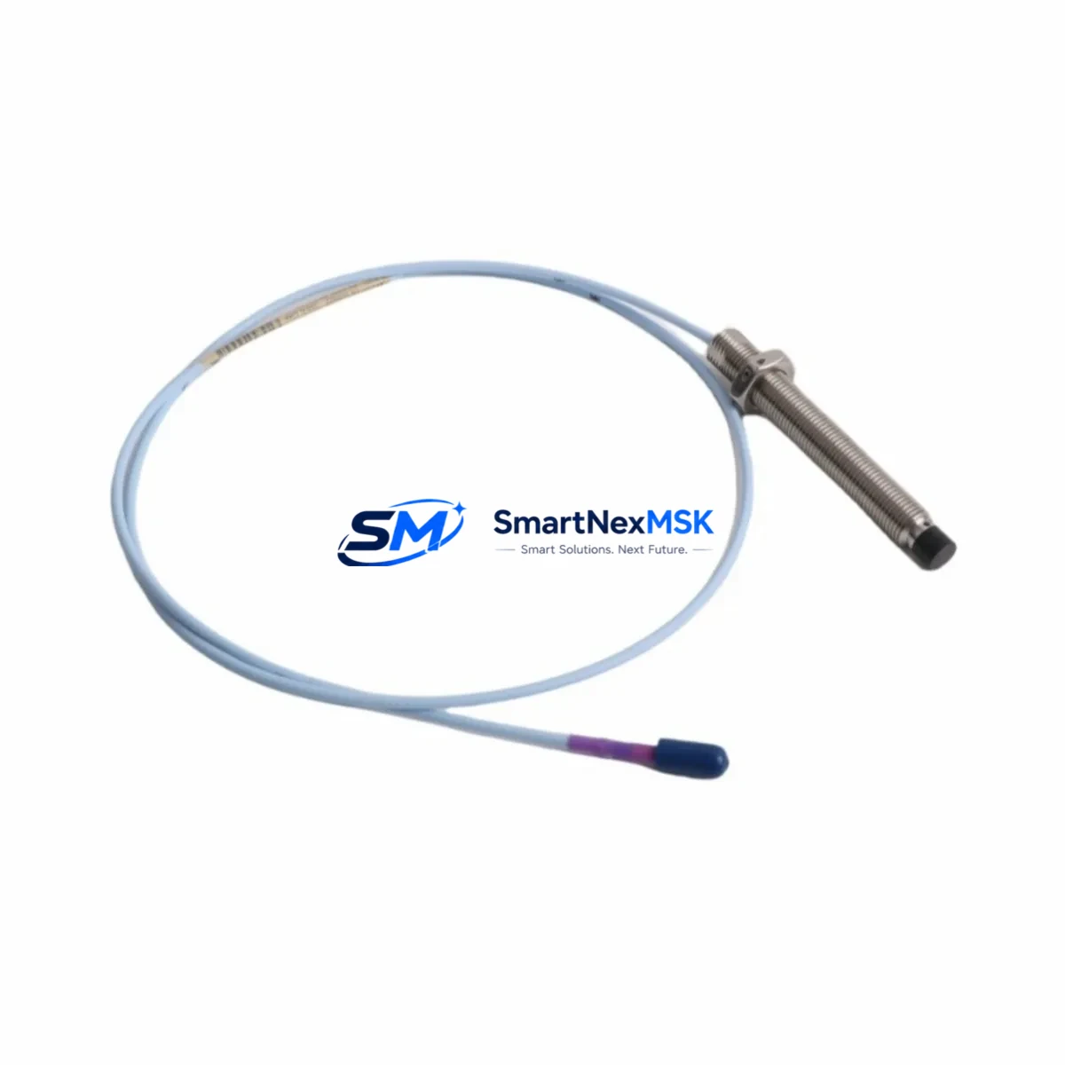
| Transducer Type | 11mm Eddy-Current Proximity Transducer |
| Cable Length | 5.0 m (extension cable compatible with 330130 series) |
| Connector Type | MIL-C-5015 style, compatible with 3300 XL monitor input terminals |
| Signal Output | -18 VDC nominal gap voltage at 1.0 mm gap (standard Bently Nevada scale factor) |
| Communication Compatibility | Analog 4–20 mA / voltage output; compatible with 3300/16 and 3300/20 monitor cards |
| Installation Requirement | Standard 11mm probe mounting boss; no bracket modification required |
| Replacement Recommendation | Direct replacement for discontinued 330703-000-026-50-02 (non-CN suffix) variants |
| Commissioning Note | Verify gap voltage at 1.0 mm using oscilloscope or Bently Nevada gap meter before energizing monitor |
| Warranty | 12 Months from date of shipment |
Retrofit Planning for Existing Automation Systems
Successful integration of the 330703-000-026-50-02-CN into an existing machinery protection architecture requires a structured pre-installation review. Begin by auditing the host monitor card — typically a Bently Nevada 3300/16 Dual Voting or 3300/20 Radial Vibration Monitor — to confirm that the channel is configured for an 11mm transducer with the standard 7.87 V/mm scale factor. If the existing installation used an earlier 7mm probe from the 330700 series, the monitor’s internal scale factor jumper or software configuration must be updated before the new transducer is commissioned.
Inspect the extension cable assembly. The 330703-000-026-50-02-CN ships with a 5-metre integral cable, and in most field installations this is joined to a 330130-series extension cable running back to the proximitor enclosure. Verify that the extension cable’s RG-58 coaxial impedance and connector pin-out match the existing field wiring before making the final termination at the 3300 XL I/O terminal block. Incorrect impedance matching introduces standing-wave reflections that degrade gap voltage linearity and trigger false high-vibration alarms on the monitor card.
At the proximitor end, confirm that the 3300 XL Proximitor — often a 330180 or 330185 module mounted in the field junction box — is powered at the correct supply voltage (typically -24 VDC from the system power supply, such as a Bently Nevada 3300/05 or equivalent rack-mount power module). A degraded power supply rail is a common root cause of transducer signal drift in aging installations and should be measured with a calibrated multimeter before the new probe is energized.
For installations where the 3300 XL rack also hosts a Keyphasor module (such as the 3300/55 Keyphasor Monitor), verify that the once-per-revolution reference signal is still correctly phased after the transducer swap. Any change in probe mounting angle relative to the shaft key or notch will shift the Keyphasor trigger point and invalidate phase-referenced vibration data used by the System 1 condition monitoring software. Similarly, if the rack includes a 3300/46 or 3300/50 Thrust Position Monitor sharing the same backplane, confirm that the backplane address switches on the replacement module match the original channel assignment to avoid monitor address conflicts during rack initialization.
Where the control system integrates Bently Nevada data into a DCS — for example via a Modbus RTU or FOUNDATION Fieldbus gateway card installed in the 3300 XL rack — no protocol reconfiguration is required for a like-for-like transducer replacement. However, if the retrofit is part of a broader migration from a legacy 3300 Series rack to a 3500 Series platform, the communication gateway, I/O mapping, and HMI faceplate tag assignments in the operator workstation will all require updating before the new rack is placed in service.
Downtime Control During System Migration
Minimizing production impact during a proximity transducer replacement on a critical rotating machine requires careful coordination between the maintenance team, the control room operator, and — where applicable — the OEM service representative. The recommended approach is to pre-stage the 330703-000-026-50-02-CN alongside all ancillary components (extension cable, proximitor, terminal block labels, and gap-setting tool) before the machine is taken offline, so that the physical swap can be completed within a single planned maintenance window.
Before de-energizing the 3300 XL monitor channel, export the current channel configuration from the System 1 software or the monitor’s front-panel display, including the alert and danger setpoints, time-delay settings, and OK relay logic. This configuration file serves as the restoration baseline and eliminates the risk of setpoint transcription errors during recommissioning. If the monitor card does not support configuration export, photograph the front-panel DIP switch positions and record all setpoint values in the maintenance work order.
During the physical swap, maintain the original program logic in the host PLC or DCS by placing the affected monitor channel in bypass mode rather than removing the I/O signal entirely. This preserves the control narrative and prevents spurious shutdowns on adjacent channels that share the same voting logic group. Once the new transducer is installed and the gap voltage is verified within the ±10% tolerance band specified in the Bently Nevada installation manual, release the bypass and confirm that the monitor’s OK LED illuminates and the vibration reading is stable before returning the machine to service.
For sites operating under ISA-18.2 alarm management standards, document the bypass duration and the as-found / as-left gap voltage readings in the site’s management of change (MOC) record. This documentation supports the 12-month warranty claim process and provides traceability for future audits.
Retrofit Support FAQ
Q1: Is the 330703-000-026-50-02-CN a direct replacement for the non-CN suffix variant?
Yes. The -CN suffix denotes the country-of-manufacture designation for customs and export documentation purposes only. The electrical specifications, mechanical dimensions, connector type, and scale factor are identical to the standard 330703-000-026-50-02. No monitor reconfiguration is required when substituting the CN variant.
Q2: What gap voltage should I expect after installation, and how do I verify it?
At a nominal 1.0 mm air gap between the probe tip and the shaft surface, the output should read approximately -18 VDC (±10%) when measured at the proximitor output terminals with the system powered. Use a calibrated digital multimeter or the Bently Nevada gap-setting tool. If the reading falls outside the tolerance band, adjust the probe axial position in 0.1 mm increments until the target voltage is achieved before locking the probe in place.
Q3: Can this transducer be used with a Bently Nevada 3500 Series monitor?
The 330703-000-026-50-02-CN is optimized for the 3300 XL platform. While the 3500 Series uses the same eddy-current measurement principle, the 3500/42M and 3500/45 monitor cards are factory-configured for the 3500-series transducer family (e.g., 330780 or 330930 series) with different scale factors and connector pinouts. Using a 3300 XL transducer on a 3500 monitor without reconfiguration will produce inaccurate readings. Consult your Bently Nevada representative before cross-platform substitution.
Q4: What does the 12-month warranty cover, and how is a claim initiated?
The 12-month warranty covers manufacturing defects, premature signal failure under normal operating conditions, and dimensional non-conformance verified against the Bently Nevada factory specification sheet. To initiate a claim, contact sales@smartnexmsk.com with the purchase order number, installation date, site name, and a description of the failure mode. Units must be returned in original packaging with the gap voltage reading recorded at the time of failure. Replacement units are typically dispatched within 5 business days of claim approval.
© 2026 SMARTNEXMSK. All rights reserved.
Original Source: https://smartnexmsk.com
Contact: sales@smartnexmsk.com | +86 18259474341


