Bently Nevada 330703-000-040-10-02-CN 3300 XL Retrofit-Ready Proximity Probe for Legacy Control Systems
The Bently Nevada 330703-000-040-10-02-CN is an 11 mm proximity probe engineered for the 3300 XL Series continuous machinery monitoring platform. As original equipment reaches end-of-life and spare parts become increasingly difficult to source, this retrofit-ready replacement provides a direct, specification-matched upgrade path for facilities operating legacy vibration monitoring systems. Whether you are restoring a failed channel, modernizing a control cabinet, or executing a planned system migration, this probe delivers the dimensional accuracy, signal integrity, and connector compatibility required for seamless integration without reprogramming or rewiring the existing signal chain.
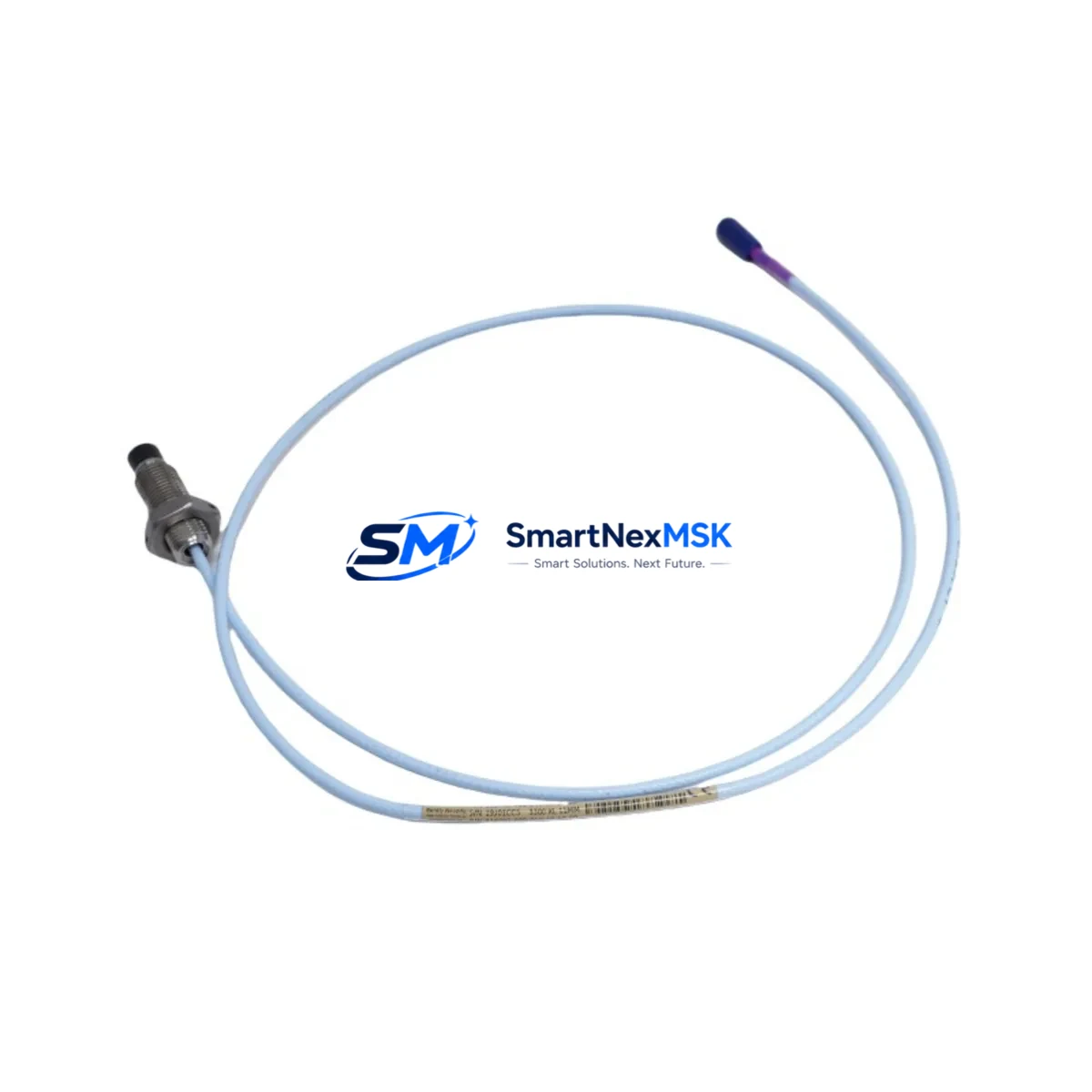
The 330703-000-040-10-02-CN is a 40-inch (approximately 1,016 mm) armored cable probe with a standard 5-meter extension cable interface. It operates within the standard Bently Nevada eddy-current sensing range and is calibrated for use with the 3300 XL proximitor/seismic transducer system. The probe tip diameter, thread specification, and connector type are fully compatible with existing probe holders, guide bushings, and junction boxes already installed in the field, eliminating the need for mechanical modifications during replacement.
Upgrade Compatibility Table
| Parameter | Specification / Compatibility Note |
|---|---|
| SKU / Part Number | 330703-000-040-10-02-CN |
| Series | Bently Nevada 3300 XL |
| Probe Tip Diameter | 11 mm — compatible with standard 3300 XL probe holders |
| Cable Length | 40 inches (armored); pairs with 5 m extension cable |
| Connector Type | Standard BNC / coaxial — no adapter required |
| Proximitor Compatibility | 3300 XL Proximitor/Seismic Transducer (e.g., 330180 series) |
| Signal Protocol | Eddy-current analog — compatible with existing 3300 XL monitor cards |
| Monitor Card Interface | Compatible with 3300/16 and 3300/20 series monitor modules |
| Installation Requirement | No mechanical modification; direct thread-in replacement |
| Commissioning Note | Gap voltage verification required after installation (typically −10 VDC ± 0.5 V) |
| Warranty | 12 months from date of shipment |
Retrofit Planning for Existing Automation Systems
Replacing a proximity probe in an operating plant requires careful coordination across multiple system layers. Before removing the failed 330703-000-040-10-02-CN or its predecessor, maintenance engineers should document the existing gap voltage reading at the proximitor output terminal and record the vibration baseline from the associated 3300/16 dual-channel vibration monitor or 3300/20 monitor module. These reference values are essential for post-installation verification and for confirming that the new probe is seated at the correct mechanical gap — typically between 1.0 mm and 2.5 mm from the shaft surface, depending on the target material and shaft diameter.
In systems where the 330703-000-040-10-02-CN feeds into a 3500 Series rack via a field wiring termination block, engineers should verify that the termination module pinout matches the probe cable shield grounding convention. Mismatched shield grounding between the probe cable and the 3500/42M proximitor I/O module is a common source of noise after replacement. If the installation uses a 3300 XL 5-meter extension cable (such as the 330130-045-00-00) to bridge the probe to the proximitor, inspect the extension cable connectors for corrosion or mechanical damage before reuse — a degraded extension cable will introduce DC offset errors that mimic a faulty probe.
For facilities migrating from older 7200 Series probes to the 3300 XL platform, the transition typically involves replacing the 7200 Series proximitor with a 3300 XL Proximitor/Seismic Transducer and updating the rack wiring to match the new I/O pinout. The 330703-000-040-10-02-CN is fully compatible with this migration path and does not require changes to the DCS tag configuration or the System 1 machinery health software database, provided the transducer scale factor (mV/mil or mV/µm) is confirmed to match the monitor card configuration.
In control cabinets where the 3300 XL rack shares a backplane with a 3300/55 temperature monitor or a 3300/65 speed and phase reference monitor, ensure that the rack power supply — typically a 3300/05 or 3300/10 power supply module — has sufficient headroom to support the additional probe channel. A fully loaded 3300 XL rack drawing near its rated output may exhibit intermittent channel faults after adding a replacement probe if the power budget is not reviewed. Similarly, if the cabinet includes a 3300 XL communication gateway for Modbus or FOUNDATION Fieldbus output, verify that the channel address mapping in the gateway configuration reflects the physical slot position of the monitor card associated with the new probe.
For sites using a Bently Nevada 1900/65A general-purpose equipment monitor as a temporary bridge during a phased migration, the 330703-000-040-10-02-CN can be connected directly to the 1900/65A input channel using the standard coaxial interface, allowing continuous vibration monitoring to remain active while the primary 3300 XL rack is serviced or upgraded. This approach is particularly effective for critical rotating equipment — compressors, turbines, and pumps — where unplanned downtime carries significant production cost.
Downtime Control During System Migration
Minimizing downtime during a proximity probe replacement begins with pre-staging all replacement components before the maintenance window opens. For the 330703-000-040-10-02-CN, this means having the replacement probe, the appropriate extension cable, a calibrated gap-setting tool, and a digital voltmeter available at the work site before the machine is taken offline. If the installation requires removal of the probe holder or guide bushing, confirm that replacement hardware is on hand — waiting for mechanical parts during an active outage is one of the most common causes of extended downtime on rotating machinery maintenance jobs.
Once the new probe is installed and the gap voltage is confirmed within specification, the monitor card channel should be reset and the OK relay output verified before the machine is restarted. In systems where the 3300 XL rack is connected to a DCS via a hardwired 4–20 mA output or a digital communication link, confirm that the DCS is receiving a valid process value on the associated tag before releasing the machine to operations. If the site uses System 1 Evolution software for online machinery diagnostics, verify that the new probe channel is trending correctly and that no latent alarms are present before closing the work order.
For planned migrations involving multiple probe replacements across a single rack, a phased approach — replacing one channel at a time while the machine remains in service — is strongly recommended over a full rack shutdown. This strategy preserves the original program logic, maintains HMI display continuity, and allows the operations team to monitor remaining channels throughout the maintenance period. Each replaced channel should be individually commissioned and signed off before proceeding to the next, with gap voltage, vibration baseline, and OK relay status documented for the maintenance record.
Retrofit Support FAQ
Q: Is the 330703-000-040-10-02-CN a direct drop-in replacement for the original Bently Nevada part?
A: Yes. This probe is manufactured to the same dimensional and electrical specification as the original 330703-000-040-10-02-CN. It uses the same thread pitch, tip diameter, cable length, and connector type, and is calibrated for use with the 3300 XL proximitor system. No mechanical modification or recalibration of the monitor card is required, provided the gap voltage is set correctly during installation.
Q: What commissioning steps are required after installation?
A: After threading the probe to the correct mechanical gap, measure the DC gap voltage at the proximitor output terminal. The target value is typically −10 VDC ± 0.5 V for a standard 3300 XL installation with a steel shaft target. Confirm the OK relay is energized and that the monitor card is displaying a valid vibration reading before returning the machine to service. Document the as-found and as-left gap voltage values in the maintenance record.
Q: Can this probe be used with older Bently Nevada monitor platforms such as the 3300 or 7200 Series?
A: The 330703-000-040-10-02-CN is optimized for the 3300 XL platform. While the eddy-current sensing principle is compatible with older 3300 Series monitors, the scale factor and OK threshold settings may differ. Consult the monitor card configuration documentation before connecting this probe to a non-XL monitor. For 7200 Series installations, a proximitor change is typically required as part of the migration.
Q: What warranty coverage is provided, and what does it include?
A: All units are covered by a 12-month warranty from the date of shipment. The warranty covers manufacturing defects and functional failures under normal operating conditions. Each unit undergoes pre-shipment functional testing, including gap voltage output verification and cable continuity check, before dispatch. Warranty claims are supported by our technical team at sales@smartnexmsk.com.
© 2026 SMARTNEXMSK. All rights reserved.
Original Source: https://smartnexmsk.com
Contact: sales@smartnexmsk.com | +86 18259474341


