Bently Nevada 330703-000-050-10-12-00 Spare for 3300 XL Automation: Precision Replacement for Vibration Monitoring Continuity
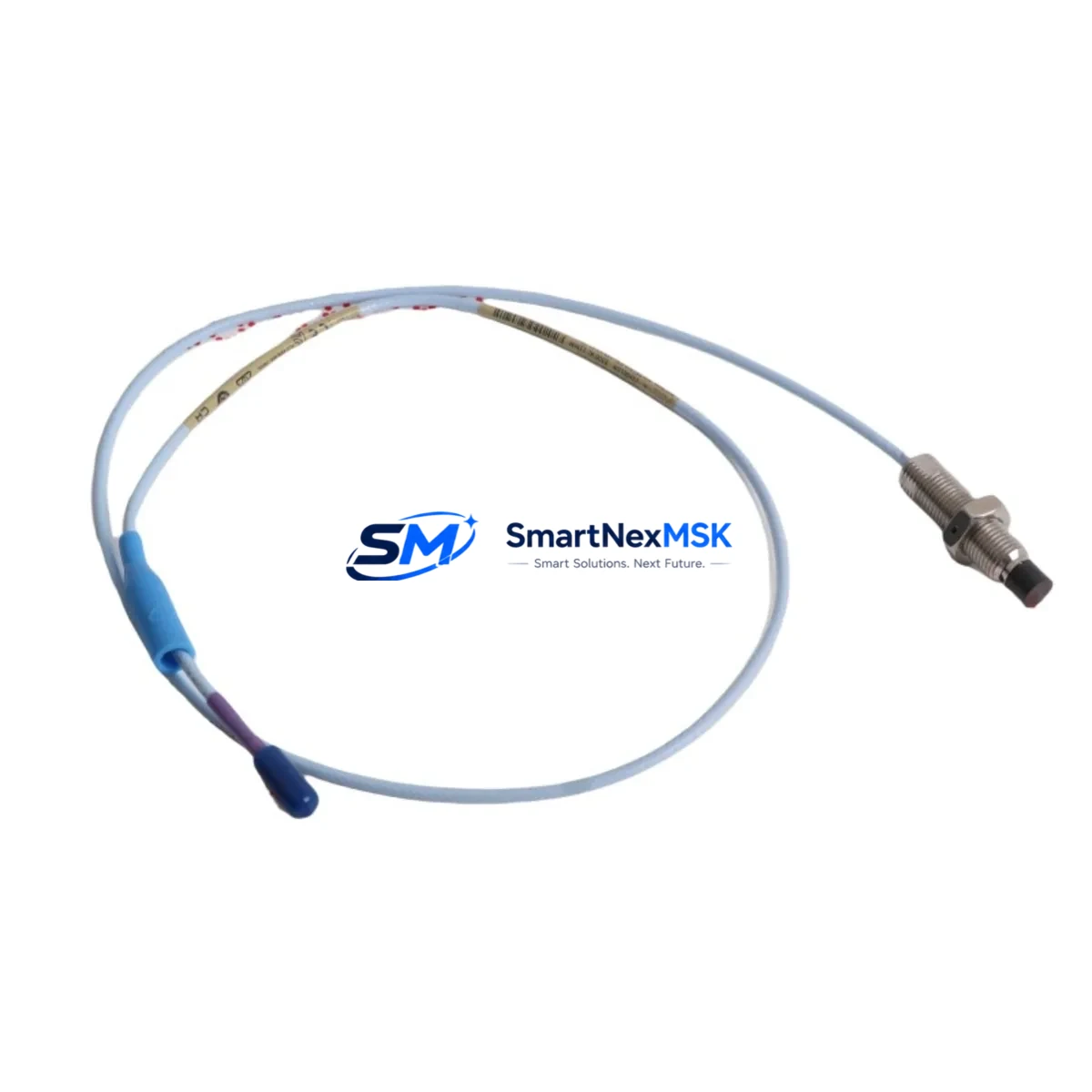
The Bently Nevada 330703-000-050-10-12-00 is an original 11mm eddy-current proximity probe engineered for the 3300 XL Series continuous vibration monitoring system. In rotating machinery protection — turbines, compressors, pumps, and gearboxes — this probe is a front-line sensor whose failure directly triggers unplanned shutdown. Maintaining a verified spare on the shelf is not optional; it is a core element of any credible predictive maintenance program.
This unit ships tested, serialized, and ready for immediate field installation. Each probe is verified for output sensitivity (nominally −7.87 V/mm), gap voltage linearity, and cable continuity before dispatch. A 12-month warranty covers manufacturing defects under normal operating conditions.
Spare Maintenance Table
| Parameter | Specification |
|---|---|
| Part Number | 330703-000-050-10-12-00 |
| Brand | Bently Nevada |
| Series | 3300 XL |
| Probe Tip Diameter | 11 mm |
| Cable Length | 5.0 m (integral) |
| Extension Cable | 10 m (suffix -10) |
| Output Sensitivity | −7.87 V/mm (nominal) |
| Linear Range | 0.25 – 2.54 mm |
| Supply Voltage | −24 VDC (via driver/proximitor) |
| Temperature Range | −35 °C to +177 °C (probe tip) |
| Target Material | AISI 4140 steel or equivalent |
| Connector | 3-pin MIL-C-5015 (standard) |
| Ingress Protection | IP67 (probe body) |
| Compatibility | 3300 XL Proximitor® 3300/16, 3300/55, 3500/42M |
| Application | Radial vibration, axial position, differential expansion |
| Warranty | 12 Months |
| Condition | Original, new-in-box or tested surplus |
Maintenance Planning for Continuous Operation
When a 330703-000-050-10-12-00 proximity probe is flagged during routine point inspection or gap voltage trending, the replacement workflow should extend beyond the probe itself. Maintenance engineers should treat this event as a trigger for a broader loop audit.
Begin with the 3300 XL Proximitor® module (typically a 3300/16 or 3300/55 driver) mounted in the monitor rack. Verify its bias voltage output and confirm the driver has not drifted outside the −18 V to −24 V supply window. A degraded proximitor will cause a new probe to read incorrectly even after installation. If the proximitor is original-generation hardware, consider stocking a replacement driver alongside the probe.
Next, inspect the 330130 extension cable connecting the probe to the proximitor. Extension cables are frequently overlooked during scheduled maintenance but are a common source of intermittent gap voltage faults, especially in high-vibration or high-temperature environments. Check the armor jacket, connector pins, and continuity end-to-end.
At the rack level, audit the 3500 Series monitor chassis — particularly the 3500/42M Proximitor/Seismic Monitor card — for alarm setpoint integrity and OK relay status. Confirm that the 3500/22M Transient Data Interface is logging correctly and that no latched faults are masking a secondary sensor fault.
For systems integrated with a System 1 Evolution or System 1 Optimizer software platform, verify that the channel configuration reflects the correct probe type, gap voltage range, and engineering unit scaling after probe replacement. A misconfigured channel will pass hardware checks but generate false alarms or missed trips.
In the broader control cabinet, check the 3500/15 Power Supply module for output ripple and voltage stability. Proximity probe systems are sensitive to supply noise; a failing power supply can mimic probe degradation symptoms. Similarly, inspect the 3500/92 Communication Gateway or Modbus/OPC interface card if the monitor feeds a DCS or SCADA historian — communication faults can prevent alarm data from reaching the control room even when the hardware is functioning correctly.
For plants running mixed Bently Nevada generations, also verify compatibility between the 330703 probe and any 3300/20 Voltage Comparator or 3300/25 Key Phasor® module in the same rack. Phase reference accuracy depends on consistent probe sensitivity across all channels.
Procurement engineers should note that the 330703-000-050-10-12-00 is a long-lead item in some regions. Stocking a minimum of two units per critical machine train — one installed, one on the shelf — is standard practice in ISO 55001-aligned maintenance programs. Pairing this spare with a 330180-51-05 proximity probe (8mm variant for tighter installations) and a set of 330130 extension cables covers the majority of 3300 XL field replacement scenarios.
Site Replacement Workflow
Step 1 — Isolation: Coordinate with the control room to place the affected channel in bypass mode via the 3500 monitor. Do not remove the probe under live alarm conditions without bypass confirmation.
Step 2 — Gap measurement: Before removing the old probe, record the installed gap voltage (target: −10.0 V ± 0.5 V for most steel targets at nominal gap). This baseline confirms whether the fault is probe-side or driver-side.
Step 3 — Probe removal: Disconnect the extension cable at the proximitor end first. Unthread the probe from the mounting bracket using the correct spanner — avoid torquing the cable armor. Note the installed gap depth (thread turns from flush) for reinstallation reference.
Step 4 — New probe installation: Thread the 330703-000-050-10-12-00 to the recorded depth. Reconnect the 330130 extension cable. Apply anti-seize compound to the probe threads if operating above 120 °C.
Step 5 — Gap verification: Power the proximitor and measure gap voltage at the driver output. Adjust probe depth until gap voltage is within the linear range (typically −10.0 V ± 0.25 V). Lock the probe with the jam nut.
Step 6 — System restore: Remove bypass, confirm OK relay status, verify alarm setpoints are active, and log the replacement in the CMMS with the new probe serial number and gap voltage reading.
This workflow applies equally when replacing an end-of-life 330703-00-050-10-12-00 (legacy part number format) with the current 330703-000-050-10-12-00, ensuring backward compatibility without system reconfiguration.
Spare Parts Support FAQ
Q: Is the 330703-000-050-10-12-00 compatible with both 3300 XL and 3500 Series monitors?
A: Yes. The 330703 probe family is designed for use with 3300 XL Proximitor drivers and is fully compatible with 3500/42M monitor cards. Confirm the driver model and supply voltage before installation to ensure the gap voltage output falls within the monitor’s input range.
Q: How is each unit tested before shipment?
A: Every probe undergoes output sensitivity verification, gap voltage linearity check across the full linear range, cable continuity test, and connector integrity inspection. A test report is available upon request. Units are shipped in anti-static packaging with protective tip caps.
Q: What is the recommended spare parts inventory strategy for a critical machine train?
A: Industry best practice for API 670-compliant installations is to maintain a minimum of one cold spare per probe channel on critical machinery. For plants with multiple 3300 XL systems, a pooled inventory of 2–4 units of the 330703-000-050-10-12-00, combined with matched extension cables and at least one spare proximitor driver, provides adequate coverage for both planned outages and emergency replacements.
Q: What does the 12-month warranty cover?
A: The warranty covers manufacturing defects, output sensitivity drift beyond published tolerances, and connector or cable assembly failures under normal operating conditions. It does not cover physical damage from improper installation, chemical exposure beyond rated limits, or target material incompatibility. Warranty claims are processed within 5 business days of receipt of the returned unit.
© 2026 SMARTNEXMSK. All rights reserved.
Original Source: https://smartnexmsk.com
Contact: sales@smartnexmsk.com | +86 18259474341


