Bently Nevada 330703-000-060-10-02-00 Maintenance-Ready Spare: Spare Replacement & Industrial Downtime Risk Control
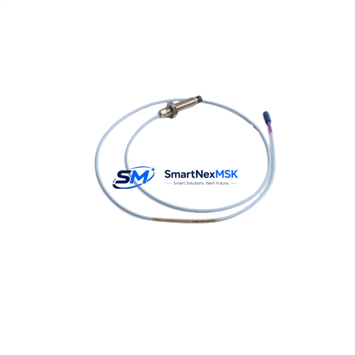
The Bently Nevada 330703-000-060-10-02-00 is an original eddy-current proximity sensor engineered for the 3300 XL Series vibration monitoring system. With an 8 mm tip diameter and a 60-inch (1524 mm) integral cable, this sensor delivers precise non-contact displacement and vibration measurements on rotating machinery — including steam turbines, gas compressors, centrifugal pumps, and large induction motors. For maintenance engineers managing critical rotating assets, holding a verified spare of this sensor is not optional; it is a fundamental element of any credible predictive maintenance or emergency response plan.
Unplanned downtime caused by a failed proximity sensor can cascade rapidly. A single degraded signal from the 330703-000-060-10-02-00 can trigger false vibration alarms, mask genuine shaft displacement anomalies, or force a protective shutdown of the entire machine train. In process industries where a compressor or turbine outage costs thousands of dollars per hour, the ability to swap a confirmed-good sensor within minutes — rather than waiting days for emergency procurement — is a direct operational and financial advantage.
Every unit supplied by SMARTNEXMSK is sourced from verified channels, individually inspected, and function-tested prior to shipment. A 12-month warranty covers each sensor against manufacturing defects and performance deviations from the original Bently Nevada specification.
Spare Maintenance Table
| Parameter | Specification |
|---|---|
| Part Number / SKU | 330703-000-060-10-02-00 |
| Brand | Bently Nevada |
| Series | 3300 XL Proximity Transducer System |
| Sensor Type | Eddy-Current Proximity Sensor |
| Tip Diameter | 8 mm |
| Cable Length | 60 inches (1524 mm) integral cable |
| Measurement Range | Typically 0–2 mm (per 3300 XL system calibration) |
| Output Signal | Voltage (DC), compatible with 3300 XL proximitor/driver |
| Compatible Driver / Proximitor | Bently Nevada 3300 XL 8 mm Proximitor (e.g., 330180 series) |
| Target Material Compatibility | Steel, stainless steel, iron-based alloys |
| Operating Temperature | -35 °C to +120 °C (sensor body) |
| Environmental Protection | Suitable for oil mist, high-humidity, and vibration-intensive environments |
| Mounting Thread | M10 × 1 (standard 3300 XL bracket compatible) |
| Origin | USA |
| Condition | Original spare — new or factory-refurbished to OEM specification |
| Pre-shipment Testing | Function-tested and verified against 3300 XL system parameters |
| Warranty | 12 months from date of shipment |
| Lead Time | In-stock: ships within 1–3 business days |
| Typical Applications | Steam turbines, gas compressors, centrifugal pumps, large motors, gearboxes |
Maintenance Planning for Continuous Operation
When a 330703-000-060-10-02-00 proximity sensor is flagged during routine vibration monitoring or a scheduled outage inspection, experienced maintenance engineers know that replacing the sensor alone is rarely sufficient for a complete and reliable restoration. The 3300 XL proximity transducer system is a tightly integrated measurement chain, and the condition of every upstream and downstream component directly affects the accuracy and reliability of the restored signal.
Begin with the Bently Nevada 330180-series Proximitor/Driver — the signal conditioning module that pairs with this sensor. A proximitor that has been exposed to sustained high temperatures, moisture ingress, or supply voltage fluctuations may produce a shifted or noisy output even when connected to a new sensor. Inspect the proximitor’s DC supply voltage (typically –24 VDC) and verify the output voltage falls within the calibrated gap range before closing the cabinet.
Next, examine the extension cable (commonly the Bently Nevada 330130 or 330140 series) that connects the sensor to the proximitor. Cable insulation breakdown, connector corrosion, or a damaged armored jacket — particularly in high-vibration or high-temperature zones — is a frequent root cause of intermittent sensor faults that are misdiagnosed as sensor failures. Replace the extension cable if continuity or insulation resistance tests reveal any anomaly.
Within the control cabinet, inspect the 3300 XL monitor card (such as the 3300/16 or 3300/20 series) that receives the proximitor output. Verify that the channel is correctly configured for the 8 mm sensor range and that the OK relay output is functioning. A monitor card with a degraded input channel can mask a genuine sensor problem or generate nuisance trips after a sensor replacement.
Check the DC power supply module feeding the proximitor. Bently Nevada 3300 XL systems typically use a dedicated –24 VDC supply; voltage ripple or a marginal supply can introduce noise into the measurement chain. If the plant uses a Bently Nevada 3500/15 Power Supply or equivalent rack-mounted supply, verify output stability under load.
For plants running integrated machinery protection, also inspect the 3500-series rack I/O modules and communication gateway cards (such as the 3500/92 or 3500/93 Modbus/TCP or OPC modules) that relay vibration data to the DCS or SCADA system. A firmware mismatch or a failed communication card can cause the newly replaced sensor’s data to appear frozen or absent at the operator workstation — a situation that is easily mistaken for a continued sensor fault.
If the machine train includes a Keyphasor transducer (e.g., Bently Nevada 330980 or 330900 series), verify its signal integrity at the same time. The Keyphasor reference signal is used for phase and 1× amplitude calculations; a degraded Keyphasor will corrupt the diagnostic value of the newly restored proximity channel.
Finally, review the terminal blocks and field wiring within the junction box and control cabinet. Loose terminations, corroded ferrules, or undersized conductors on the sensor signal wiring are a common source of high-frequency noise that appears as elevated broadband vibration on the monitor display. Torque all terminals to specification and verify shield grounding continuity at a single point.
Maintaining a small, curated spare parts kit — including at least one 330703-000-060-10-02-00 sensor, one matched extension cable, and a spare proximitor — reduces mean time to repair (MTTR) for proximity system faults from days to under two hours on most sites.
Site Replacement Workflow
Step 1 — Isolation and documentation. Before removing the existing sensor, record the current gap voltage from the monitor or proximitor output. This baseline reading confirms the original installation gap and provides a reference for the replacement setup. Isolate the channel at the monitor card (do not de-energize the entire rack unless required by site safety procedures) and lock out the field junction box.
Step 2 — Physical removal. Unscrew the sensor from its mounting bracket using the appropriate spanner. Note the number of turns required to reach the original gap — this is a useful starting reference for the replacement. Inspect the bracket threads and the target area on the shaft for wear, corrosion, or mechanical damage.
Step 3 — Installation of the 330703-000-060-10-02-00 replacement. Thread the new sensor into the bracket and adjust the gap to achieve the target output voltage specified in the 3300 XL calibration record (typically –10 VDC at the nominal gap for an 8 mm sensor). Use a calibrated gap tool or a feeler gauge to verify physical clearance before locking the sensor in position with the locknut.
Step 4 — Signal verification. With the channel re-enabled at the monitor, verify that the OK LED is illuminated, the gap voltage is within the linear range, and the channel is not in alarm. Compare the static reading against the pre-removal baseline. A deviation greater than ±0.5 VDC warrants investigation of the extension cable, proximitor, or target surface condition before returning the machine to service.
Step 5 — System compatibility confirmation. Confirm that the replacement sensor’s part number suffix matches the original — specifically the cable length code (060 = 60 inches) and the connector type (02 = standard). Substituting a sensor with a different cable length without recalibrating the system will introduce a scale error in the displacement reading.
Step 6 — Return to service and documentation. Update the maintenance management system (CMMS) with the replacement date, new sensor serial number, and post-installation gap voltage. Schedule a follow-up vibration trend review at 24 and 72 hours after restart to confirm stable operation.
Spare Parts Support FAQ
Q1: Is the 330703-000-060-10-02-00 a direct drop-in replacement for older Bently Nevada 3300 XL proximity sensors?
Yes. The 330703-000-060-10-02-00 is the current standard 8 mm, 60-inch cable proximity sensor for the 3300 XL system and is backward-compatible with all 3300 XL proximitor/driver modules. No firmware changes or reconfiguration of the monitor card are required, provided the replacement sensor matches the original part number suffix exactly. Always verify the cable length and connector codes before installation.
Q2: How does SMARTNEXMSK verify the condition of spare sensors before shipment?
Each 330703-000-060-10-02-00 unit undergoes a pre-shipment functional test that includes DC resistance measurement of the sensor coil, insulation resistance check on the integral cable, and output voltage verification when connected to a reference 3300 XL proximitor at the nominal gap distance. Units that do not meet OEM specification are rejected. A test report is available upon request for critical applications.
Q3: What is the recommended spare parts inventory strategy for a plant operating multiple 3300 XL systems?
For plants with three or more 3300 XL-monitored machine trains, industry best practice recommends holding a minimum of two 330703-000-060-10-02-00 sensors per site, along with one matched extension cable set and one spare proximitor module. This inventory level supports same-shift replacement for a single-channel fault without triggering an emergency procurement event. For critical machines with no installed redundancy, consider increasing the on-hand quantity to three sensors.
Q4: What does the 12-month warranty cover, and what is the claims process?
The 12-month warranty covers manufacturing defects, coil open/short failures, cable insulation breakdown, and connector failures under normal operating conditions. It does not cover damage caused by incorrect installation gap, mechanical impact, or operation outside the specified temperature range. To initiate a warranty claim, contact sales@smartnexmsk.com with the order number, installation date, and a brief description of the observed fault. Replacement units are dispatched within 3 business days of claim approval.
© 2026 SMARTNEXMSK. All rights reserved.
Original Source: https://smartnexmsk.com
Contact: sales@smartnexmsk.com | +86 18259474341


