Bently Nevada 330703-000-060-10-11-05 Spare 3300 XL Automation
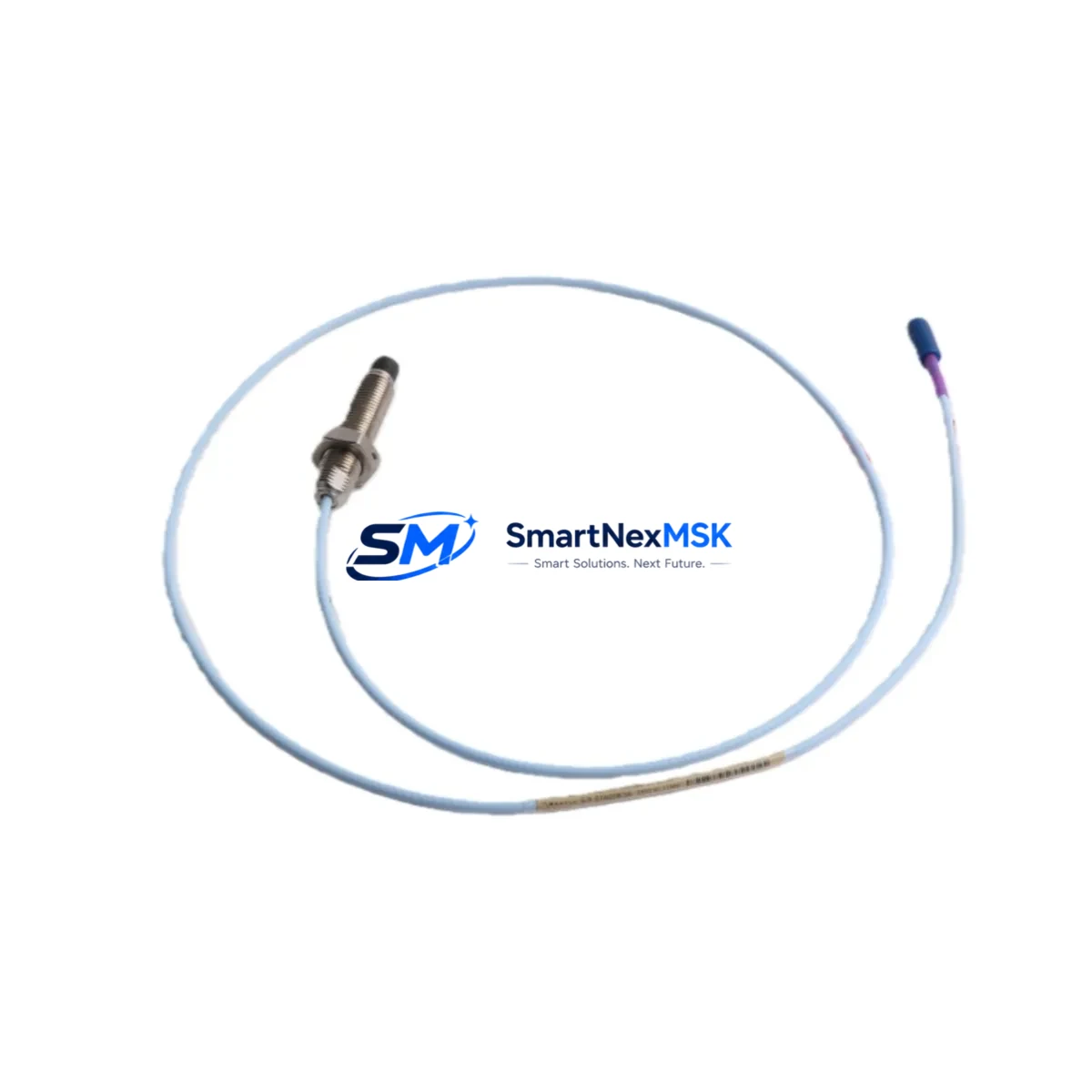
The Bently Nevada 330703-000-060-10-11-05 is an 8mm eddy-current proximity probe engineered for the 3300 XL Monitoring System — one of the most widely deployed vibration and position monitoring platforms in rotating machinery protection. As a maintenance-ready original spare, this probe is critical for facilities that cannot afford unplanned downtime on turbines, compressors, pumps, and gearboxes where shaft vibration and axial position monitoring are mandatory for safe operation.
For maintenance engineers managing aging machinery protection systems, having a verified replacement for the 330703-000-060-10-11-05 on the shelf is not optional — it is a core element of any credible predictive maintenance (PdM) or reliability-centered maintenance (RCM) program. This probe ships tested, calibrated, and ready for immediate installation, reducing mean time to repair (MTTR) and restoring continuous monitoring capability without delay.
Spare Maintenance Table
| Parameter | Specification |
|---|---|
| SKU / Part Number | 330703-000-060-10-11-05 |
| Brand | Bently Nevada |
| Series | 3300 XL Monitoring System |
| Probe Type | Eddy-Current Proximity Probe |
| Probe Diameter | 8mm |
| Cable Length | 60 inches (5 ft) — encoded in SKU suffix -060 |
| Connector Type | 10-32 UNF, standard 3300 XL interface |
| Operating Temperature | -35°C to +177°C (probe tip) |
| Sensitivity | 200 mV/mil (7.87 V/mm) nominal |
| Linear Range | Approx. 0–80 mil (0–2 mm) |
| Target Material Compatibility | Steel, stainless steel, iron-based alloys |
| System Compatibility | Bently Nevada 3300 XL, 3300/16, 3300/20 monitor cards |
| Application | Shaft radial vibration, axial position, differential expansion |
| Installation Environment | Industrial — turbines, compressors, pumps, gearboxes |
| Condition | Original spare, pre-shipment tested |
| Warranty | 12 Months |
| Origin | USA |
Maintenance Planning for Continuous Operation
When a 330703-000-060-10-11-05 proximity probe requires replacement, experienced maintenance engineers know that the probe itself is only one element of a complete eddy-current measurement chain. A thorough site inspection and spare parts review should cover the full signal path to prevent repeat failures and ensure measurement accuracy is restored to specification.
Start with the extension cable — typically the 330130-series or 330730-series Bently Nevada extension cables — which connects the probe to the proximitor/driver. Extension cables are subject to mechanical fatigue, connector corrosion, and insulation breakdown in high-temperature or high-vibration environments. Replace or test the extension cable whenever the probe is changed. Next, inspect the proximitor/driver module (such as the 3300 XL 8mm proximitor, part series 330180 or 330780) mounted in the junction box or control cabinet. A failed or drifting proximitor will produce incorrect gap voltage even with a new probe installed.
At the monitor card level, verify the 3300/16 or 3300/20 vibration monitor card in the rack for alarm setpoint integrity, OK relay status, and buffered output signal quality. If the system uses a 3300/55 or 3300/65 keyphasor module, confirm that the keyphasor signal is clean and properly phased — a degraded keyphasor will corrupt 1X and 2X vibration vectors across all channels in the rack. For facilities running System 1 condition monitoring software, verify that the channel configuration and transducer type settings match the replacement probe’s sensitivity and gap range.
In the control cabinet, check the DC power supply rails feeding the 3300 XL rack — typically –24 VDC. Voltage sag or ripple on the supply will directly affect proximitor output linearity. Inspect terminal blocks and field wiring for corrosion, loose terminations, and shield grounding continuity. For installations in hazardous areas, confirm that Zener barrier or galvanic isolator modules (such as MTL or P+F signal isolators) are within calibration and have not degraded. These isolators are often overlooked during probe replacements but are a common source of signal offset errors.
If the machine is a steam turbine or gas turbine with differential expansion monitoring, also inspect the thrust position probe on the opposing end of the shaft — typically another 330703-series or 330705-series probe — since thrust bearing wear often affects both axial channels simultaneously. For compressor trains, review the condition of seismic velocity sensors or accelerometers mounted on bearing housings, as these provide complementary vibration data that cross-validates the proximity probe readings.
A complete spare parts kit for a 3300 XL proximity measurement loop should include: the probe (330703-000-060-10-11-05), the matching extension cable, the proximitor module, spare terminal block connectors, and at minimum one spare monitor card per rack type. Procurement engineers should establish a minimum stock level of two probes per critical machine train to support both planned outage replacement and emergency breakdown response.
Site Replacement Workflow
Step 1 — Pre-shutdown verification: Record the existing gap voltage (typically –10 VDC ±0.5 V at nominal air gap) and buffered output waveform from the monitor card before shutdown. This baseline confirms whether the existing probe has failed or whether the fault lies elsewhere in the measurement chain.
Step 2 — Isolation and lockout: Follow site LOTO procedures. De-energize the proximitor supply at the rack power distribution terminal. Do not disconnect the probe under live voltage — this can damage the proximitor input circuit.
Step 3 — Probe removal: Unscrew the probe from the probe holder using the correct spanner. Note the installed gap (number of turns from flush) for reference during reinstallation. Inspect the probe tip for impact damage, contamination, or thermal discoloration that may indicate a root cause beyond normal wear.
Step 4 — New probe installation: Thread the 330703-000-060-10-11-05 replacement probe into the holder. Set the air gap to the manufacturer-specified nominal gap (typically 50 mil / 1.27 mm for 8mm probes) using a non-ferrous feeler gauge or by measuring gap voltage with a calibrated DC voltmeter. Target gap voltage: –10.0 VDC ±0.25 V.
Step 5 — System verification: Re-energize the proximitor supply. Confirm OK LED status on the monitor card. Verify gap voltage, alarm setpoints, and buffered output signal on the oscilloscope or System 1 software. Document the as-left gap voltage and waveform for the maintenance record.
Step 6 — Return to service: Clear the monitor card alarm, confirm no latched trips, and return the machine to normal operation. Update the CMMS work order with the replacement probe serial number and as-left gap voltage.
This workflow is compatible with direct replacement of legacy 330703-series probes and supports system continuity without firmware changes or monitor card reconfiguration, provided the replacement probe matches the original sensitivity specification.
Spare Parts Support FAQ
Q1: Is the 330703-000-060-10-11-05 a direct drop-in replacement for older 330703-series probes?
Yes. The 330703-000-060-10-11-05 is backward compatible with all 3300 XL 8mm proximity measurement systems. The SKU suffix encodes cable length (-060 = 60 inches), connector style (-10), jacket material (-11), and temperature rating (-05). Verify that your existing extension cable and proximitor match the same series before installation. No monitor card reconfiguration is required for a like-for-like replacement.
Q2: What pre-shipment testing is performed on this spare?
Each unit undergoes electrical continuity verification, insulation resistance testing, and gap voltage output confirmation against a calibrated steel target before dispatch. A test report is available upon request. Units are individually packaged to prevent tip damage during transit.
Q3: How should this probe be stored in a spare parts inventory?
Store in original packaging in a dry, temperature-controlled environment (10°C–35°C), away from strong magnetic fields and mechanical vibration. Inspect connector pins and probe tip annually. Recommended maximum shelf life before re-testing: 3 years. For long-term storage programs, vacuum-sealed packaging with desiccant is advised.
Q4: What is the warranty coverage and what does it include?
This spare carries a 12-month warranty from the date of shipment, covering manufacturing defects and electrical performance failures under normal operating conditions. Warranty does not cover damage from incorrect installation, mechanical impact, or operation outside specified environmental limits. Replacement or refund is processed within 5 business days of confirmed fault diagnosis. Contact sales@smartnexmsk.com for warranty claims.
© 2026 SMARTNEXMSK. All rights reserved.
Original Source: https://smartnexmsk.com
Contact: sales@smartnexmsk.com | +86 18259474341


