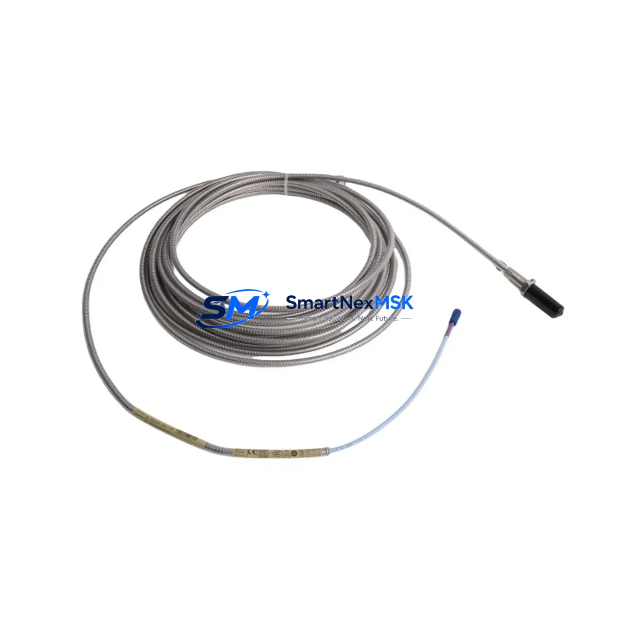
Bently Nevada 330704-000-070-10-01-CN Retrofit-Ready Proximity Probe for 3300 XL Control Systems
The Bently Nevada 330704-000-070-10-01-CN is an 11mm eddy-current proximity probe engineered for seamless integration into legacy and active Bently Nevada 3300 XL vibration monitoring systems. Whether you are replacing a failed sensor on a critical rotating machine, upgrading an aging control cabinet, or migrating from an obsolete 3300 Series platform to a modernized 3300 XL architecture, this probe delivers the dimensional accuracy, signal linearity, and environmental resilience required for continuous plant operation.
Industrial facilities operating gas turbines, steam turbines, compressors, pumps, and gearboxes rely on the 3300 XL system for real-time shaft displacement and vibration measurement. When a probe reaches end-of-life or a spare is no longer available through the original channel, procurement teams face pressure to source a verified replacement quickly — without compromising measurement integrity or triggering a full system recalibration. The 330704-000-070-10-01-CN is stocked and tested to address exactly this scenario.
Each unit ships with a 12-month warranty and passes pre-shipment functional verification, including gap voltage linearity checks and insulation resistance testing, ensuring it is ready for immediate field installation.
Upgrade Compatibility Table
| Parameter | Detail |
|---|---|
| SKU / Part Number | 330704-000-070-10-01-CN |
| Brand | Bently Nevada |
| Series Compatibility | 3300 XL (primary); 3300 Series (verify driver pairing) |
| Probe Tip Diameter | 11 mm |
| Cable Length | 1.0 m (integral cable) |
| Extension Cable Pairing | 330130-045-00-CN or equivalent 3300 XL extension cable |
| Driver / Proximitor Pairing | 3300 XL 8mm/11mm Proximitor® (e.g. 330180-X1-05) |
| Mounting Thread | M14 × 1.5 (standard 3300 XL bracket) |
| Gap Voltage (nominal) | −10 VDC at 1.0 mm gap |
| Communication / Signal | Analog voltage output; compatible with 3500 rack I/O via signal conditioner |
| Installation Requirement | Verify bracket clearance, target material (steel preferred), and grounding continuity |
| Retrofit Recommendation | Replace probe + extension cable as a matched set for optimal linearity |
| Commissioning Focus | Gap setting, OK relay verification, Proximitor output voltage check |
| Warranty | 12 Months from shipment date |
Retrofit Planning for Existing Automation Systems
A successful retrofit begins well before the probe arrives on site. Engineers planning a 3300 XL sensor replacement should audit the full measurement chain: the 330704-000-070-10-01-CN probe, the paired 330130 series extension cable, and the 3300 XL Proximitor® module mounted in the field junction box. If the Proximitor is also aged or showing drift, replacing it alongside the probe eliminates a common source of post-installation calibration discrepancy.
For facilities running a Bently Nevada 3500 Series rack-based monitoring system in parallel with field-mounted 3300 XL sensors, confirm that the I/O module — typically a 3500/42M or 3500/40M position monitor card — is configured to accept the analog voltage range produced by the 11mm probe at the intended gap. If the rack was previously calibrated for an 8mm probe, the scale factor in the monitor configuration must be updated before the new probe is commissioned.
Control cabinet upgrades often involve replacing the 3300 XL power supply module at the same time. Verify that the cabinet’s 24 VDC rail can support the combined current draw of all active Proximitor units after the retrofit. Undersized power supplies are a frequent cause of intermittent OK relay trips during the first weeks of operation following a sensor upgrade.
For plants migrating from older Bently Nevada 7200 Series or 3000 Series probes, the physical mounting thread and target gap distance differ. A new mounting bracket machined to M14 × 1.5 specification is required, and the target surface should be inspected for runout and surface finish before the new probe is gapped. Shaft runout exceeding the probe’s linear range will produce false vibration readings regardless of probe condition.
When the control system includes a System 1 software platform for condition monitoring, update the channel configuration to reflect the new probe’s scale factor and OK voltage thresholds. Failure to update System 1 channel parameters after a probe swap is a common source of nuisance alarms during the first operational cycle. If the facility also uses a Bently Nevada TK-3 portable calibrator or equivalent field verification tool, perform a bench gap-voltage sweep on the replacement probe before installation to confirm linearity across the full measurement range.
I/O expansion projects that add new measurement points to an existing 3500 rack should also account for the 3500/20 rack interface module and any required Modbus or FOUNDATION Fieldbus gateway if the new channels must report to a DCS or SCADA platform. Ensuring protocol compatibility before the probe is installed prevents costly rework during the commissioning phase.
Downtime Control During System Migration
Minimizing unplanned downtime during a proximity probe replacement requires a structured pre-outage checklist. Before isolating the measurement channel, capture a baseline vibration trend from the existing probe using the plant historian or System 1 software. This baseline serves as the acceptance reference after the new 330704-000-070-10-01-CN is installed and gapped.
Where the process permits, use the 3500 rack’s channel bypass function to hold the last valid reading while the probe is being swapped. This prevents a spurious trip signal from propagating to the DCS and triggering an unplanned shutdown. Coordinate with the control room operator before activating bypass mode and confirm the bypass timeout setting is sufficient for the planned swap duration.
After installation, perform the gap voltage check at the Proximitor output terminals before restoring the channel to active monitoring. Confirm the OK relay energizes and the vibration reading is within the expected baseline range. Document the as-found and as-left gap voltage, probe serial number, and installation date in the plant maintenance management system. This record supports future warranty claims and simplifies the next planned replacement interval.
For critical machines where even a brief monitoring gap is unacceptable, consider installing a temporary portable vibration monitor — such as a Bently Nevada SCOUT 100 or equivalent handheld analyzer — on an adjacent measurement plane during the swap. This provides continuous vibration visibility on the shaft while the permanent channel is offline, preserving the plant’s ability to detect developing faults without interruption.
Retrofit Support FAQ
Q1: Is the 330704-000-070-10-01-CN a direct drop-in replacement for my existing 3300 XL probe?
In most cases, yes. The probe uses the standard M14 × 1.5 mounting thread and is designed for the 3300 XL Proximitor® driver. However, always verify the cable length, extension cable part number, and Proximitor model before ordering. If your existing installation uses a non-standard bracket or a modified cable assembly, confirm dimensional compatibility with your maintenance drawings.
Q2: Does this probe require recalibration of the 3500 rack after installation?
If you are replacing a like-for-like 11mm probe on the same measurement channel, the rack configuration typically does not require changes. However, if the channel was previously configured for a different probe diameter or a different scale factor, update the monitor card parameters in System 1 or the rack keypad before returning the channel to service. Always perform a gap voltage verification at the Proximitor output after installation.
Q3: What wiring checks should I perform before powering up the new probe?
Verify continuity and insulation resistance on the extension cable before connecting the Proximitor. Check that the shield drain wire is grounded at one end only (typically at the Proximitor enclosure) to avoid ground loops. Confirm the coaxial connector is fully seated and the locking nut is torqued to the manufacturer’s specification. Inspect the target area for debris or surface damage that could affect the gap measurement.
Q4: What does the 12-month warranty cover, and how is it claimed?
The 12-month warranty covers manufacturing defects and functional failures under normal operating conditions. It does not cover damage resulting from incorrect installation, overvoltage, mechanical impact, or use outside the specified environmental ratings. To initiate a warranty claim, contact our sales team with the unit serial number, purchase date, and a description of the failure. We will arrange return shipping and provide a replacement or repair within the agreed lead time.
© 2026 SMARTNEXMSK. All rights reserved.
Original Source: https://smartnexmsk.com
Contact: sales@smartnexmsk.com | +86 18259474341


