Bently Nevada 330730-040-00-05 Spare for 3300 XL Automation: Precision Replacement for Vibration Monitoring Continuity
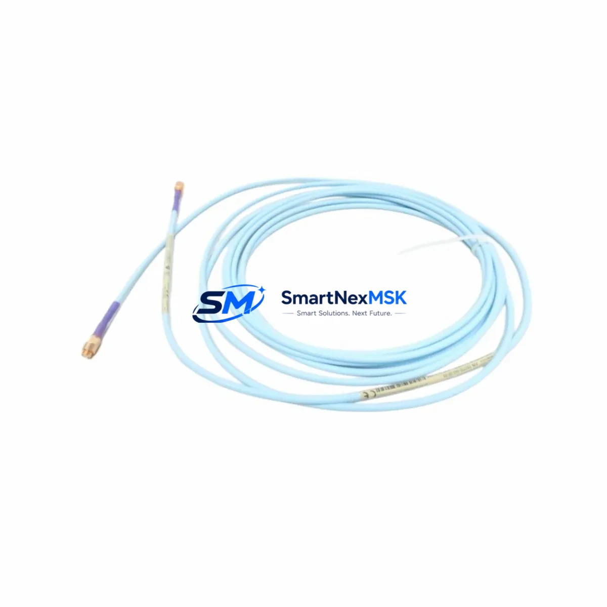
The Bently Nevada 330730-040-00-05 is a factory-specification proximity extension cable engineered for the 3300 XL Series vibration monitoring system. With a cable length of 5 metres (16.4 ft) and an 11 mm probe interface, this extension cable forms the critical signal path between the eddy-current proximity probe and the 3300 XL monitor rack. Any degradation in this cable — whether from insulation fatigue, connector corrosion, or mechanical damage — directly compromises shaft displacement and vibration readings, triggering nuisance trips or, worse, masking genuine machinery faults.
For maintenance engineers managing rotating equipment such as steam turbines, gas compressors, centrifugal pumps, and large induction motors, keeping a verified spare of the 330730-040-00-05 on the shelf is a non-negotiable element of a sound predictive maintenance programme. Unplanned downtime caused by a failed extension cable can cost far more than the cable itself; having a tested, ready-to-install replacement eliminates that risk entirely.
Spare Maintenance Table
| Parameter | Specification |
|---|---|
| Part Number / SKU | 330730-040-00-05 |
| Brand | Bently Nevada |
| Series | 3300 XL Vibration Monitoring System |
| Product Type | Proximity Extension Cable |
| Probe Interface | 11 mm Eddy-Current Proximity Probe |
| Cable Length | 5 m (16.4 ft) |
| Connector Type | Coaxial, factory-terminated |
| Signal Type | Analogue DC voltage (proximity / displacement) |
| Compatible Monitors | 3300 XL 11 mm Proximity System monitors |
| Operating Temperature | –40 °C to +85 °C (cable); probe end per probe spec |
| Installation Environment | Industrial — turbine halls, compressor skids, motor control rooms |
| Origin | USA |
| Condition | Original, new / surplus stock |
| Pre-shipment Testing | Continuity, impedance, and connector integrity verified |
| Warranty | 12 Months |
Maintenance Planning for Continuous Operation
When a 330730-040-00-05 extension cable is flagged during a control-cabinet inspection or a routine vibration channel check, experienced maintenance engineers know that the cable is rarely the only component that warrants attention. A systematic inspection of the entire measurement loop is essential to restore full system integrity and prevent repeat failures.
Begin at the probe end: the companion Bently Nevada 330101-00-08-10-02-00 (or equivalent 3300 XL 11 mm proximity probe) should be inspected for tip damage, thread condition, and gap voltage. A probe that has been running at the edge of its linear range will stress the extension cable’s signal path. Next, verify the 3300 XL proximitor / oscillator-demodulator (such as the 330180-91-00) — check its output voltage, power supply rail, and housing seal, as a failing proximitor can mimic a cable fault and vice versa.
At the monitor rack, inspect the 3300/16 or 3300/20 monitor card slot for bent pins, oxidised contacts, and correct seating. The 3300 XL power supply module feeding the rack should be load-tested; an under-voltage condition degrades the entire channel’s accuracy. If the cabinet houses a Bently Nevada 3500 Series rack alongside the 3300 XL system, cross-check the inter-rack wiring and common-ground bonding — ground loops are a frequent source of spurious vibration readings that are incorrectly attributed to cable faults.
For plants running Emerson DeltaV or Honeywell Experion DCS platforms, confirm that the 4–20 mA output signal conditioner or signal isolator downstream of the proximitor is within calibration. A drifting isolator will corrupt the vibration trend data even after a perfect cable replacement. Similarly, inspect the terminal block assemblies in the junction box between the field probe and the control room — loose or corroded terminations account for a significant proportion of intermittent channel faults.
Finally, if the plant uses a System 1 Evolution or equivalent condition-monitoring software platform, verify that the channel configuration (gap voltage limits, full-scale range, engineering-unit scaling) matches the replacement cable’s electrical characteristics before returning the loop to service. Document the as-found and as-left gap voltages to support future trend analysis.
Site Replacement Workflow
Step 1 — Isolate and document. Before removing the 330730-040-00-05, record the as-found gap voltage at the proximitor output and photograph the cable routing, connector orientation, and any cable-tie or conduit entry points. This baseline is essential for post-replacement verification.
Step 2 — Remove the failed cable. Disconnect the coaxial connectors at both the probe and the proximitor ends using the correct spanner size to avoid damaging the connector bodies. Inspect the mating connectors on the probe and proximitor for corrosion, thread damage, or contamination before installing the replacement.
Step 3 — Install the 330730-040-00-05 spare. Route the new cable following the original path, maintaining minimum bend radius and avoiding proximity to high-voltage power cables or variable-frequency drive (VFD) output conductors. Torque connectors to the manufacturer’s specification — over-tightening is a common cause of premature connector failure.
Step 4 — Verify gap voltage and channel output. Power up the proximitor and measure the DC gap voltage. For an 11 mm probe system, the nominal gap voltage at the recommended installation gap is typically in the –10 V to –18 V range (confirm against the specific probe datasheet). Adjust the probe gap if necessary. Confirm the monitor channel reads correctly and that no alarms or danger trips are active.
Step 5 — Return to service and update records. Log the replacement in the CMMS (Maximo, SAP PM, or equivalent), update the spare-parts inventory, and order a replacement spare to restore buffer stock. A single-unit buffer for each critical vibration channel is the minimum recommended holding for continuous-process plants.
Spare Parts Support FAQ
Q1: Is the 330730-040-00-05 compatible with both the 3300 XL and the older 3300 Series monitors?
The 330730-040-00-05 is designed and specified for the 3300 XL 11 mm proximity system. Compatibility with earlier 3300 (non-XL) monitors depends on the specific monitor card revision and proximitor model in use. We recommend confirming the monitor card part number before ordering. Our technical team can assist with compatibility verification prior to shipment.
Q2: How is each unit tested before shipment?
Every 330730-040-00-05 unit undergoes pre-shipment inspection covering coaxial connector continuity, cable insulation integrity, and mechanical condition of both terminations. Units that do not meet original-specification standards are not dispatched. A 12-month warranty covers defects in materials and workmanship from the date of shipment.
Q3: What is the recommended spare-parts holding strategy for 3300 XL proximity cables?
For continuous-process facilities (refineries, power generation, petrochemical), the industry-standard recommendation is to hold a minimum of one spare extension cable per critical machine train, plus a general pool spare for non-critical trains. Given the lead times associated with OEM procurement channels, maintaining a local buffer of 2–3 units of the 330730-040-00-05 is advisable for plants with multiple 3300 XL-monitored machines.
Q4: Can you supply long-term or blanket-order quantities for MRO programmes?
Yes. We support MRO procurement programmes with scheduled releases, consignment stock arrangements, and multi-unit pricing. Contact our sales team to discuss volume requirements, lead times, and documentation packages (test reports, material certificates) for your procurement records.
© 2026 SMARTNEXMSK. All rights reserved.
Original Source: https://smartnexmsk.com
Contact: sales@smartnexmsk.com | +86 18259474341


