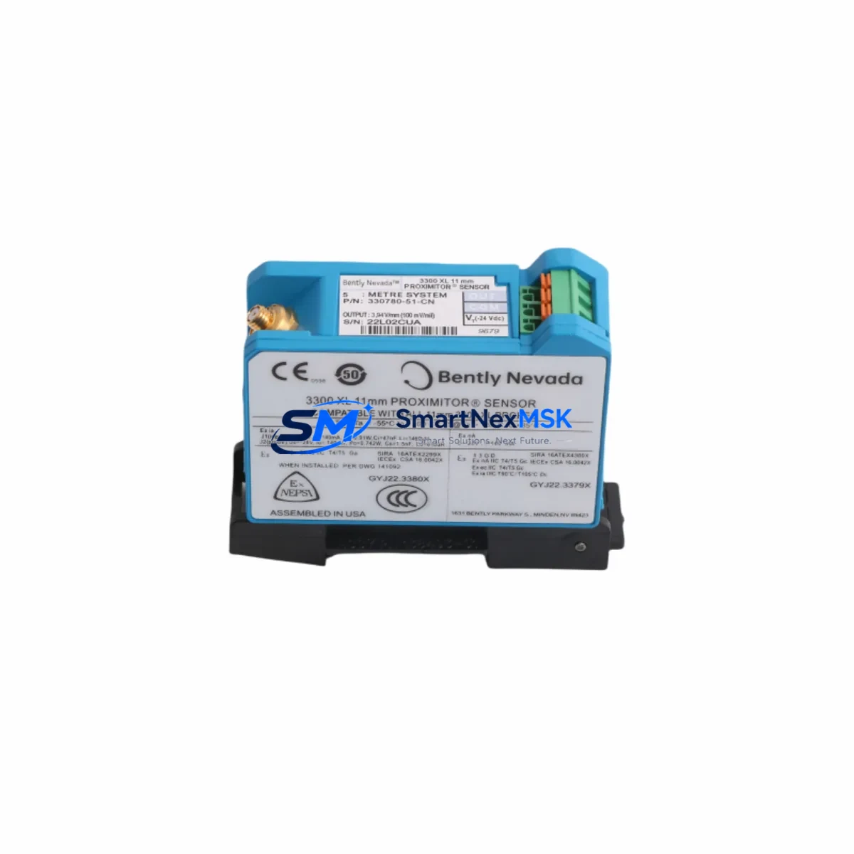
Bently Nevada 330780-51-CN Retrofit-Ready Proximitor for 3300 XL Control Systems
The Bently Nevada 330780-51-CN is a high-precision eddy current proximitor sensor engineered for seamless integration into legacy 3300 XL Series vibration monitoring systems. As industrial facilities face increasing pressure to extend the operational life of existing machinery protection infrastructure, the 330780-51-CN delivers a verified drop-in upgrade path that eliminates the need for full system replacement. Whether you are managing a turbine protection rack, a compressor monitoring cabinet, or a rotating equipment health platform, this proximitor is designed to restore full measurement integrity with minimal engineering intervention.
The 330780-51-CN operates within the standard Bently Nevada eddy current measurement chain, accepting a compatible extension cable and probe assembly — typically an 330130 or 330180 series probe paired with a 330130 or 330190 extension cable — to complete the transducer loop. The proximitor conditions the raw probe signal and outputs a calibrated DC voltage proportional to the gap between the probe tip and the observed target surface. This output is directly compatible with the 3300 XL monitor inputs, including the 3300/16 and 3300/20 series rack-mounted monitors, without requiring signal conditioning adapters or firmware reconfiguration.
Before installing the 330780-51-CN into an existing rack, engineers should verify the power supply capacity of the 3300 XL rack’s internal power module. The proximitor draws regulated power from the rack backplane, and aging power modules — particularly the 3300/05 power supply — may exhibit voltage droop under full channel load. Confirming that the backplane voltage remains within the ±24 VDC specification under load is a critical pre-installation step. If the power module is marginal, replacement with a current-production equivalent should be completed before the proximitor swap to avoid nuisance trips or measurement drift post-commissioning.
Terminal wiring for the 330780-51-CN follows the standard Bently Nevada color-coded convention: the probe signal wire connects to the designated input terminal on the monitor card, while the shield and common are landed at the rack terminal block per the original loop drawing. Engineers migrating from an older 7200 Series proximitor or a non-Bently eddy current transmitter should pay particular attention to the common reference potential — mismatched commons between the proximitor output and the monitor card input are a frequent source of offset errors and false alarm conditions during initial commissioning. A continuity check of the shield drain wire from the junction box back to the rack common terminal is recommended before energizing the loop.
For facilities running a DCS or safety instrumented system that reads the 3300 XL monitor’s 4–20 mA output or relay contacts, no changes to the control system configuration are required when replacing the proximitor. The monitor card — such as the 3300/55 or 3300/46 — continues to process the proximitor output and generate the same scaled analog output and trip relay signals. However, if the facility’s historian or condition monitoring platform (such as a System 1 Evolution node) is configured with probe-specific calibration coefficients, the calibration record should be reviewed to confirm that the 330780-51-CN’s sensitivity factor matches the stored value. A mismatch of even 50 mV/mil can introduce a measurable offset in the vibration trend data.
In retrofit projects involving communication protocol migration — for example, transitioning from a hardwired relay interface to a Modbus RTU or FOUNDATION Fieldbus link via a 3500 Series gateway — the 330780-51-CN can serve as the sensor-layer foundation while the monitor and communication infrastructure is upgraded in stages. This phased approach allows the facility to maintain continuous machinery protection on critical assets such as steam turbines, centrifugal compressors, and boiler feed pumps while the upper layers of the monitoring architecture are modernized. The 3500/22M monitor, for instance, can accept the same proximitor signal and provide enhanced communication options without requiring probe or cable replacement.
Field commissioning of the 330780-51-CN follows the standard Bently Nevada gap voltage verification procedure. With the machine at rest and the probe installed at the nominal gap, the proximitor output should read within the linear range — typically between −10 VDC and −18 VDC depending on the probe type and gap setting. A Bently Nevada 330180 or 330130 probe set to a 50-mil nominal gap should produce approximately −10.4 VDC at the proximitor output terminal. This reading should be recorded in the loop calibration record and compared against the monitor card’s configured OK limits before the system is returned to service. Any deviation exceeding ±0.5 VDC from the expected value warrants investigation of the probe tip condition, extension cable integrity, and proximitor power supply voltage before sign-off.
Upgrade Compatibility Table
| Parameter | Detail |
|---|---|
| SKU / Part Number | 330780-51-CN |
| Compatible Series | Bently Nevada 3300 XL, 3500 Series (with adapter) |
| Replaces / Upgrades | 330780-50-00, 330780-51-00, 7200 Series Proximitors |
| Sensor Type | Eddy Current Proximitor (Non-contact displacement) |
| Output Signal | DC Voltage, −10 VDC to −18 VDC (gap-dependent) |
| Power Supply | ±24 VDC from rack backplane (3300/05 or equivalent) |
| Compatible Probes | 330130, 330180, 330190 Series |
| Compatible Extension Cables | 330130, 330190 Series |
| Compatible Monitors | 3300/16, 3300/20, 3300/46, 3300/55 |
| Backplane Interface | Standard 3300 XL rack slot (no adapter required) |
| Communication Compatibility | Analog output via monitor card; Modbus RTU / FF via 3500 gateway |
| Installation Requirement | Verify rack power, terminal wiring, and gap voltage before energizing |
| Commissioning Check | Gap voltage verification per Bently Nevada loop calibration procedure |
| Origin | CN |
| Warranty | 12 Months from date of shipment |
Retrofit Planning for Existing Automation Systems
A successful 330780-51-CN retrofit begins well before the maintenance window opens. The engineering team should pull the existing loop drawings and confirm the rack slot assignment, module address, and OK relay wiring for the channel being replaced. In a typical 3300 XL rack, each proximitor occupies a dedicated slot and is addressed by physical position — there is no software-based module addressing as found in newer platforms. This means the replacement unit can be inserted into the same slot without any configuration change to the monitor card or the DCS I/O mapping.
The retrofit bill of materials for a single-channel replacement typically includes the 330780-51-CN proximitor, a replacement 330130 or 330180 probe if the existing probe shows tip wear or thread damage, a fresh section of 330190 extension cable if the existing cable has been subject to mechanical stress or chemical exposure, and a set of terminal block ferrules for the rack landing. If the rack’s 3300/05 power supply module has not been replaced within the last five years, it is prudent to include a spare in the staging area even if the current output voltage is within specification — power supply failures during a planned outage are a common source of unplanned downtime extension.
For facilities that also operate a System 1 Evolution condition monitoring node connected to the 3300 XL rack via a serial or Ethernet gateway, the retrofit plan should include a brief verification step to confirm that the historian is receiving valid data on the affected channel after the proximitor swap. The System 1 node stores probe-specific sensitivity coefficients, and if the replacement proximitor has a slightly different sensitivity factor, the trend data will show a step change at the time of replacement. Documenting this in the maintenance record prevents future confusion during trend analysis.
Where the retrofit scope extends beyond a single proximitor to include monitor card replacement — for example, upgrading from a 3300/16 to a 3300/20 to gain additional channel density — the wiring termination at the rack terminal block must be reviewed against the new monitor card’s pinout. The 3300/20 uses a different terminal assignment for the OK relay output compared to the 3300/16, and failure to update the relay wiring will result in a loss of the machinery protection trip function on that channel. A pre-energization continuity check of the OK relay circuit is mandatory in this scenario.
Downtime Control During System Migration
Minimizing downtime during a proximitor replacement requires a disciplined pre-outage preparation process. All replacement components — the 330780-51-CN, probe, extension cable, and any rack accessories — should be staged, inspected, and verified against the purchase order before the machine is taken offline. A bench test of the proximitor using a portable signal simulator confirms that the unit is functional before it enters the rack, eliminating the risk of discovering a defective unit after the machine is already shut down.
During the outage, the existing proximitor should be removed with the rack power de-energized to protect both the technician and the monitor card input circuitry. The replacement 330780-51-CN is inserted into the same slot, the probe and extension cable are reconnected at the junction box, and the rack is re-energized. The gap voltage is then verified at the proximitor output terminal before the monitor card’s OK limits are re-enabled. This sequence — de-energize, replace, re-energize, verify — typically takes less than 45 minutes for a single-channel replacement by an experienced technician, keeping the machine offline window well within the planned maintenance schedule.
For critical assets where even a brief loss of vibration monitoring is unacceptable, a temporary bypass relay can be installed across the monitor card’s trip output to maintain the machinery protection logic in a safe state during the swap. The bypass must be removed and the trip circuit verified before the machine is returned to service. This procedure should be documented in the facility’s management of change system and approved by the responsible engineer before the outage begins. Maintaining the original program logic and HMI display configuration throughout the swap — with no changes to setpoints, alarm limits, or display tags — ensures that the control room operator sees a seamless transition when the channel returns to service.
Retrofit Support FAQ
Q: Is the 330780-51-CN a direct drop-in replacement for the 330780-50-00?
A: Yes. The 330780-51-CN is functionally equivalent to the 330780-50-00 and 330780-51-00 and installs into the same 3300 XL rack slot without modification. The output signal range, power supply requirements, and probe compatibility are identical. The “-CN” suffix denotes the country of manufacture and does not affect performance or interchangeability.
Q: What wiring checks are required before energizing the replacement proximitor?
A: Verify that the probe signal wire, extension cable shield, and common reference are landed correctly at the rack terminal block per the original loop drawing. Confirm that the shield drain wire is continuous from the junction box to the rack common terminal. Check that the backplane power supply voltage is within ±24 VDC specification under load before inserting the proximitor.
Q: How is commissioning verified after the 330780-51-CN is installed?
A: With the machine at rest and the probe set to the nominal gap, measure the DC voltage at the proximitor output terminal. The reading should fall within the expected range for the probe type and gap setting — typically between −10 VDC and −18 VDC. Compare this value against the loop calibration record. If the reading is outside the expected range by more than ±0.5 VDC, inspect the probe tip, extension cable, and power supply before returning the channel to service.
Q: What warranty coverage is provided with the 330780-51-CN?
A: Every 330780-51-CN shipped by SMARTNEXMSK carries a 12-month warranty from the date of shipment. Units are functionally tested prior to dispatch. In the event of a warranty claim, contact our technical support team with the purchase order number and a description of the fault. Replacement or repair will be arranged with priority handling to minimize impact on your facility’s maintenance schedule.
© 2026 SMARTNEXMSK. All rights reserved.
Original Source: https://smartnexmsk.com
Contact: sales@smartnexmsk.com | +86 18259474341


