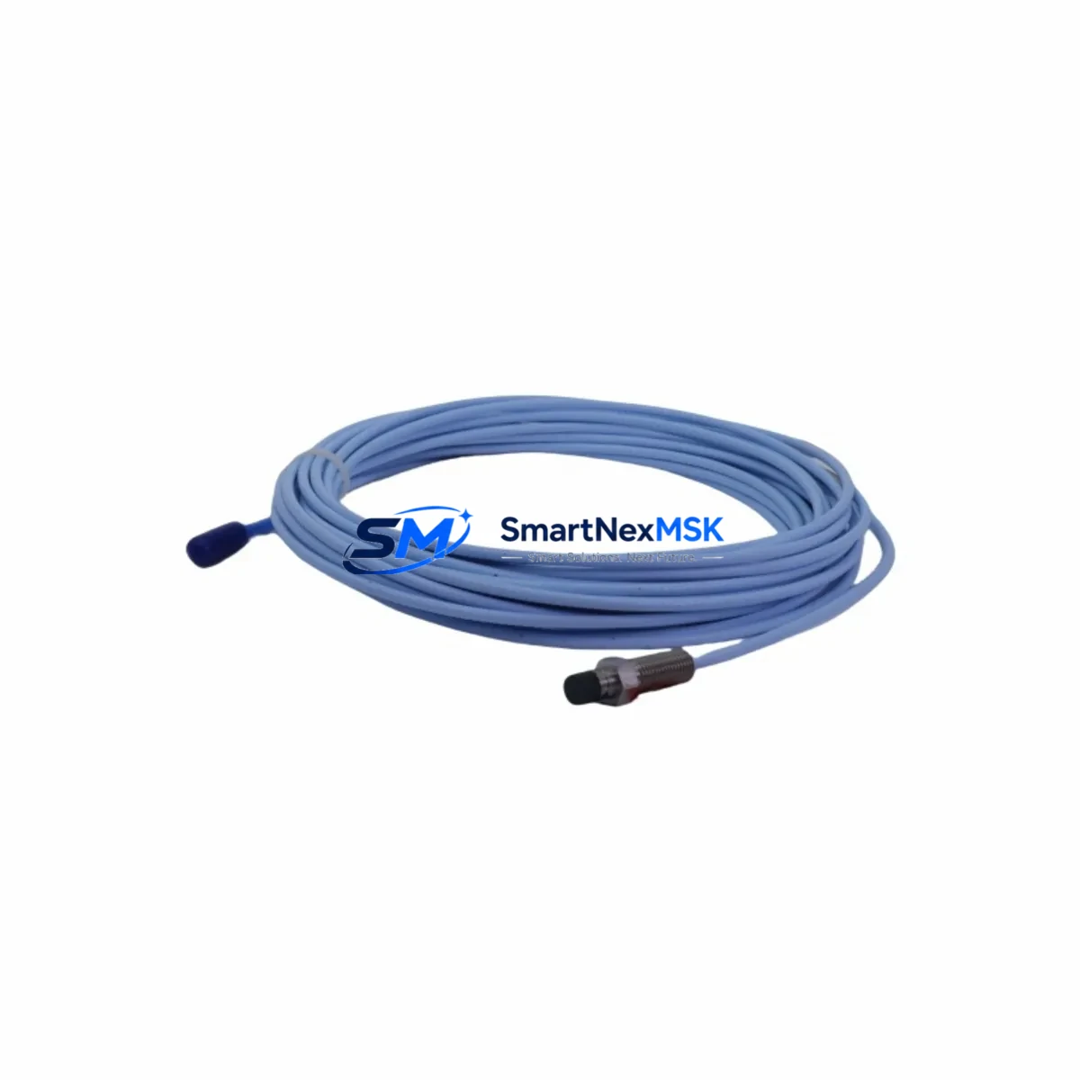
Bently Nevada 330881-16-00-200-06-02 Retrofit-Ready Proximity Transducer for 3500 Series Control Systems
The Bently Nevada 330881-16-00-200-06-02 is a PROXPAC XL proximity transducer assembly engineered for seamless integration into Bently Nevada 3500 Series machinery protection systems. As legacy 7200 Series and 3300 Series installations reach end-of-life, this module provides a verified, drop-in retrofit path that preserves existing wiring infrastructure while delivering the measurement accuracy and signal conditioning demanded by modern turbomachinery protection platforms. With a 200 mm cable extension, 6 mm probe tip, and standard -02 connector configuration, the 330881-16-00-200-06-02 is stocked and tested for immediate deployment in critical rotating equipment applications including steam turbines, gas compressors, centrifugal pumps, and large induction motors.
Upgrade Compatibility Table
| Parameter | 330881-16-00-200-06-02 (Replacement) | Legacy 7200 / 3300 Series (Original) |
|---|---|---|
| Series Compatibility | 3500 Series (primary); 3300 Series (with adapter) | 7200 Series, 3300 Series |
| Probe Tip Diameter | 6 mm | 5 mm / 8 mm (model-dependent) |
| Cable Length | 200 mm extension | Varies by suffix |
| Connector Type | -02 standard BNC-compatible | -00 / -01 (verify before ordering) |
| Supply Voltage | -24 VDC (from 3500/20 or 3500/22 power supply) | -24 VDC (dedicated 7200 power conditioner) |
| Output Signal | -18 VDC nominal (gap voltage) | -18 VDC nominal |
| Mounting / Backplane | 3500 rack backplane (3500/05 or 3500/05-01) | 7200 rack / 3300 rack (not interchangeable) |
| Communication | Hardwired analog to 3500/40M or 3500/42M monitor | Hardwired analog to 7200 monitor |
| Retrofit Recommendation | Direct replacement for 330880 / 330181 series with cable length verification | Requires gap re-calibration after swap |
| Commissioning Note | Re-gap to 1.0 mm nominal; verify OK/Alert/Danger setpoints in rack configuration | Original gap setting may differ |
| Warranty | 12 Months — covers manufacturing defects and signal performance | N/A (discontinued) |
Retrofit Planning for Existing Automation Systems
Successful replacement of the 330881-16-00-200-06-02 in a live plant environment requires a structured pre-outage engineering review. Begin by auditing the existing 3500 rack configuration: confirm the installed 3500/05 or 3500/05-01 rack backplane revision, identify the monitor module type (typically a 3500/40M Proximitor Monitor or 3500/42M Proximitor/Seismic Monitor), and document the current I/O module assignments across all rack slots. If the plant is migrating from a 7200 Series rack, the 7200/20 power conditioner and 7200/32 monitor must be decommissioned and replaced with the corresponding 3500 Series equivalents before the new transducer assembly can be commissioned.
Terminal wiring adaptation is a critical step. The 330881-16-00-200-06-02 uses a -02 connector termination; verify that the field junction box and interconnecting cable are compatible before pulling the old probe. In many brownfield installations, the existing armored extension cable from a 330130 or 330180 series probe can be reused if the cable length and connector suffix match. Where cable replacement is necessary, the 330130-080-00-00 or 330130-045-00-00 extension cables are common retrofit companions stocked alongside this assembly.
For plants running a 3500/22M power supply module, confirm that the total transducer load on the -24 VDC bus does not exceed the module’s rated output after adding the new PROXPAC XL assembly. In multi-channel racks where the 3500/40M monitors share a common power rail with 3500/60 temperature monitors or 3500/70 position monitors, a power budget calculation is mandatory. The 3500/15 or 3500/15-02 I/O module associated with the target monitor slot must also be inspected for terminal block condition and re-torqued to specification during the outage window.
Communication and program compatibility should be validated before the outage. If the 3500 rack communicates to a DCS or safety system via the 3500/92 communication gateway (Modbus or Ethernet/IP), confirm that the channel address mapping for the replaced transducer channel remains unchanged in the gateway configuration. Plants using a System 1 Evolution condition monitoring platform should verify that the point configuration for the affected measurement point reflects the new transducer sensitivity (typically 7.87 V/mm for standard PROXPAC XL assemblies) to avoid false alert conditions after restart. HMI faceplate displays tied to the vibration or position measurement should be reviewed in the SCADA or DCS engineering station prior to energizing the new module.
Downtime Control During System Migration
Minimizing unplanned downtime during a proximity transducer retrofit begins with pre-staging all replacement components — including the 330881-16-00-200-06-02 assembly, spare 3500/15 I/O modules, terminal ferrules, and calibration tools — at the work site before the maintenance window opens. A parallel verification bench test using a 3500 rack simulator or a portable PROXPAC calibration kit allows the replacement assembly to be confirmed functional before installation, eliminating the risk of discovering a defective unit mid-outage.
During the swap, bypass the affected channel in the 3500/40M monitor using the rack’s built-in bypass function to prevent spurious trips on adjacent channels while the probe is disconnected. Document the original gap voltage reading from the monitor’s front-panel display or System 1 trend before removing the old assembly; this value serves as the baseline for re-gapping the new probe. After mechanical installation and re-gapping to the 1.0 mm nominal air gap, restore the channel from bypass and observe the gap voltage stabilize within the OK band before releasing the machine to operations. The entire channel swap — from isolation to release — can typically be completed within a two-hour maintenance window when all materials are pre-staged and the engineering review is complete.
Original program logic in the DCS or safety instrumented system (SIS) does not require modification for a like-for-like transducer replacement, provided the monitor channel address and sensitivity factor are unchanged. This preserves control continuity and eliminates the need for a management-of-change (MOC) review of the control strategy, significantly reducing the administrative burden of the retrofit project.
Retrofit Support FAQ
Q1: Is the 330881-16-00-200-06-02 a direct replacement for the 330880-16-00-200-06-02?
A: Yes. The 330881 series supersedes the 330880 series PROXPAC assemblies. The mechanical dimensions, connector type, and electrical characteristics are identical. No wiring changes are required; however, a gap re-calibration is recommended after installation to confirm the output voltage is within the OK band defined in the 3500/40M monitor configuration.
Q2: Can this assembly be used in a 7200 Series rack without modification?
A: No. The 330881-16-00-200-06-02 is designed for the 3500 Series rack and monitor ecosystem. Installing it in a 7200 Series rack requires a full rack migration to 3500 Series hardware, including the 3500/05 rack, 3500/22M power supply, and the appropriate 3500/40M or 3500/42M monitor module. Direct installation into a 7200 rack is not supported.
Q3: What commissioning checks are required after installation?
A: After mechanical installation and re-gapping, verify the gap voltage at the 3500/40M monitor front panel (target: approximately -10.0 VDC at 1.0 mm gap on standard target material). Confirm OK/Alert/Danger setpoints are correctly configured in the rack software. Check the System 1 or DCS point configuration for correct sensitivity factor entry. Perform a functional test by slowly varying the gap and confirming the monitor responds correctly before releasing the channel from bypass.
Q4: What does the 12-month warranty cover?
A: The 12-month warranty covers manufacturing defects, signal performance outside published specifications, and connector integrity under normal operating conditions. Each unit is bench-tested prior to shipment to verify gap voltage output, cable continuity, and connector seating. Warranty claims are supported with a replacement unit dispatched within 3 business days of fault confirmation.
© 2026 SMARTNEXMSK. All rights reserved.
Original Source: https://smartnexmsk.com
Contact: sales@smartnexmsk.com | +86 18259474341


