Bently Nevada 330902-00-15-10-02-05 3300 XL NSv Retrofit: Compatible Upgrade for Legacy Control Systems
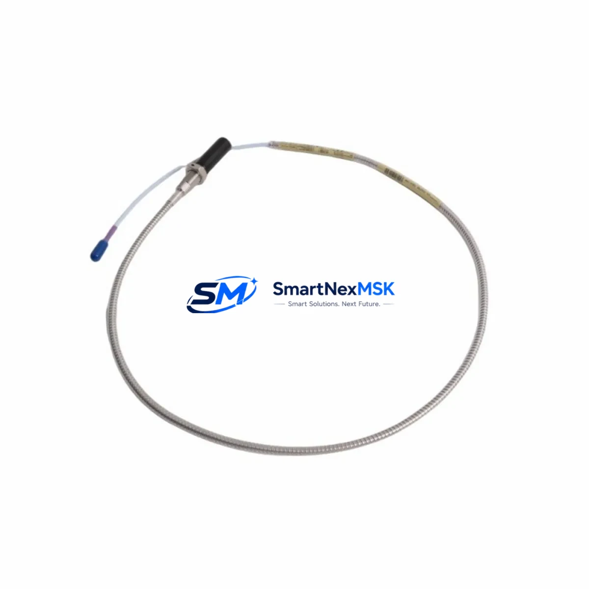
The Bently Nevada 330902-00-15-10-02-05 is a precision proximity transducer system from the 3300 XL NSv series, engineered for continuous shaft vibration and position monitoring in rotating machinery. As legacy 3300 Series installations approach end-of-life or face discontinued spare parts availability, this module serves as a verified retrofit-ready replacement for existing 3300 XL proximity transducer assemblies deployed across turbines, compressors, pumps, and critical rotating equipment in oil & gas, power generation, and heavy industrial environments.
This unit is fully tested prior to shipment, backed by a 12-month warranty, and available from in-stock inventory for rapid deployment. Whether you are executing a planned control system upgrade, responding to an unplanned failure, or building a strategic spare parts buffer, the 330902-00-15-10-02-05 provides a direct, low-risk path to restoring or modernizing your machinery protection infrastructure.
Upgrade Compatibility Table
| Parameter | Details |
|---|---|
| SKU / Part Number | 330902-00-15-10-02-05 |
| Series | Bently Nevada 3300 XL NSv |
| Function | Proximity Transducer System (Eddy-Current) |
| Probe Cable Length | 15 ft (4.6 m) — suffix -15 |
| Extension Cable Length | 10 ft (3.0 m) — suffix -10 |
| Driver / Oscillator | NSv (Non-Standard Voltage) driver module |
| Mounting / Interface | Compatible with 3300 XL monitor rack and standard Bently Nevada terminal blocks |
| Communication Compatibility | Analog 4–20 mA output; compatible with 3500 Series monitors via signal conditioning adapters |
| Replacement Scope | Direct replacement for 330902 family variants; verify cable suffix before ordering |
| Commissioning Notes | Confirm gap voltage, sensitivity (V/mm or V/mil), and driver compatibility before installation |
| Warranty | 12 Months — covers manufacturing defects and functional failure under normal operating conditions |
Retrofit Planning for Existing Automation Systems
Retrofitting a Bently Nevada proximity transducer system requires careful coordination across multiple hardware layers. The 330902-00-15-10-02-05 integrates directly into existing 3300 XL monitor racks, but engineers must verify the complete signal chain before replacement. The probe assembly connects through a matched 3300 XL extension cable to the 3300 XL NSv driver, which in turn feeds the vibration monitor channel. If the existing driver is a standard voltage (Sv) variant rather than NSv, the driver module must also be replaced to maintain calibration accuracy.
In many retrofit scenarios, the 3500/42M Proximitor Monitor or 3500/40M Proximitor Monitor is already installed in the rack alongside the transducer system. Engineers should confirm that the monitor’s channel configuration matches the NSv sensitivity curve (typically 7.87 V/mm or 200 mV/mil) before finalizing the swap. If the plant is migrating from an older 7200 Series proximity system to the 3300 XL platform, additional signal conditioning and rack reconfiguration will be required.
Terminal block wiring is a critical checkpoint. The 3300 XL terminal board must be inspected for correct pin assignments — particularly the Probe, Common, and Driver supply lines. Mislabeled or corroded terminals are a common source of commissioning delays in aging control cabinets. Where the existing cabinet uses a 3300/16 I/O module or legacy 3300/55 Proximitor, the wiring harness may need to be re-terminated to match the 3300 XL connector standard.
For plants running System 1 condition monitoring software, the transducer replacement should be logged as a configuration change event. The software’s transducer database entry for the affected channel must be updated to reflect the new part number, sensitivity, and cable lengths. If the plant uses a TDXnet or Ethernet-based data acquisition module for remote monitoring, verify that the channel mapping remains intact after the hardware swap.
Power supply capacity is another key consideration. The 3300 XL NSv driver draws power from the rack’s internal bus. If the rack is already near its power budget — particularly in dense configurations with multiple 3500 Series I/O modules or 3500/22M Transient Data Interface cards — a power audit should be completed before adding or replacing transducer channels. In some cases, a supplemental 3500/15 Power Supply module may be required.
Downtime Control During System Migration
Minimizing unplanned downtime is the primary operational concern when replacing proximity transducer systems on live rotating equipment. The recommended approach is to pre-stage the 330902-00-15-10-02-05 assembly — including the matched extension cable and NSv driver — and complete all bench testing before the maintenance window begins. This includes verifying the gap voltage output at the driver connector using a calibrated voltmeter and confirming the sensitivity curve against the original factory specification sheet.
During the physical swap, the original program logic in the 3500 Series monitor or connected DCS controller should not be modified. The transducer replacement is a hardware-layer change; the monitor’s alarm setpoints, danger thresholds, and OK relay logic should remain unchanged unless a deliberate recalibration is planned. This protects the integrity of the existing control narrative and prevents inadvertent alarm suppression during the transition period.
If the plant’s safety instrumented system (SIS) is interlocked with the vibration monitor output, the SIS logic should be placed in bypass mode — with appropriate management of change (MOC) documentation — for the duration of the swap. Once the new transducer is installed and the gap voltage is confirmed within the acceptable range (typically –10 VDC ± 0.5 V for NSv systems), the bypass can be lifted and the channel returned to normal monitoring service.
HMI faceplate verification is the final step before returning the equipment to service. Operators should confirm that the vibration trend display for the affected channel is updating correctly and that the historical data buffer has not been corrupted by the channel interruption. In System 1 environments, a short data validation period of 15–30 minutes under normal operating load is recommended before closing the work order.
Retrofit Support FAQ
Q1: Is the 330902-00-15-10-02-05 a direct drop-in replacement for other 330902 variants?
The 330902 family shares a common probe body and connector standard, but cable lengths and driver type (Sv vs. NSv) vary by suffix. The -00-15-10-02-05 suffix specifies a 15 ft probe cable, 10 ft extension cable, and NSv driver. Before ordering, confirm that your existing driver module is also NSv-rated. Mixing Sv and NSv components will result in calibration errors and may trigger false alarms.
Q2: What commissioning checks are required after installation?
After physical installation, measure the static gap voltage at the driver output with the shaft stationary. For NSv systems, the target gap is typically –10 VDC ± 0.5 V at the recommended probe-to-shaft gap (typically 1.0–1.5 mm depending on shaft material). Confirm the OK LED on the monitor channel is illuminated and that the vibration reading is within the expected baseline range for the machine at rest. Document the as-found and as-left gap voltages in the maintenance record.
Q3: Can this transducer be used with a 3500 Series monitor instead of a 3300 XL monitor?
Yes, with appropriate signal conditioning. The 3300 XL NSv driver output is compatible with 3500 Series Proximitor Monitor inputs when the monitor channel is configured for the correct sensitivity (200 mV/mil or 7.87 V/mm). Verify the channel configuration in the 3500 rack software before connecting the transducer. No hardware modification to the transducer assembly is required.
Q4: What does the 12-month warranty cover?
The 12-month warranty covers manufacturing defects and functional failure under normal operating conditions from the date of shipment. It does not cover damage resulting from incorrect installation, overvoltage, mechanical impact, or use outside the specified environmental ratings. All units are functionally tested prior to shipment. In the event of a warranty claim, contact our technical support team with the part number, serial number, and a description of the failure mode.
© 2026 SMARTNEXMSK. All rights reserved.
Original Source: https://smartnexmsk.com
Contact: sales@smartnexmsk.com | +86 18259474341


