Bently Nevada 330902-00-95-02-00 Maintenance-Ready Spare for 3300 XL Automation
The Bently Nevada 330902-00-95-02-00 is an original 8mm eddy current proximity probe engineered for the 3300 XL Series continuous machinery monitoring system. In rotating machinery protection environments — turbines, compressors, pumps, and gearboxes — this probe is a front-line sensor responsible for radial shaft vibration measurement and position monitoring. When this component degrades or fails, the entire protection loop is compromised, triggering unplanned shutdowns and exposing critical assets to damage. Maintaining a certified spare on the shelf is not optional; it is a fundamental element of any serious predictive maintenance and reliability program.
This listing provides maintenance engineers and procurement teams with a tested, original-specification 330902-00-95-02-00 probe, ready for immediate deployment. Each unit is inspected prior to shipment, verified against Bently Nevada 3300 XL system compatibility requirements, and backed by a 12-month warranty covering manufacturing defects and functional performance. Fast dispatch and reliable international logistics ensure that your downtime window stays as short as possible.
Spare Maintenance Table
| Parameter | Specification |
|---|---|
| Part Number / SKU | 330902-00-95-02-00 |
| Brand | Bently Nevada |
| Series | 3300 XL |
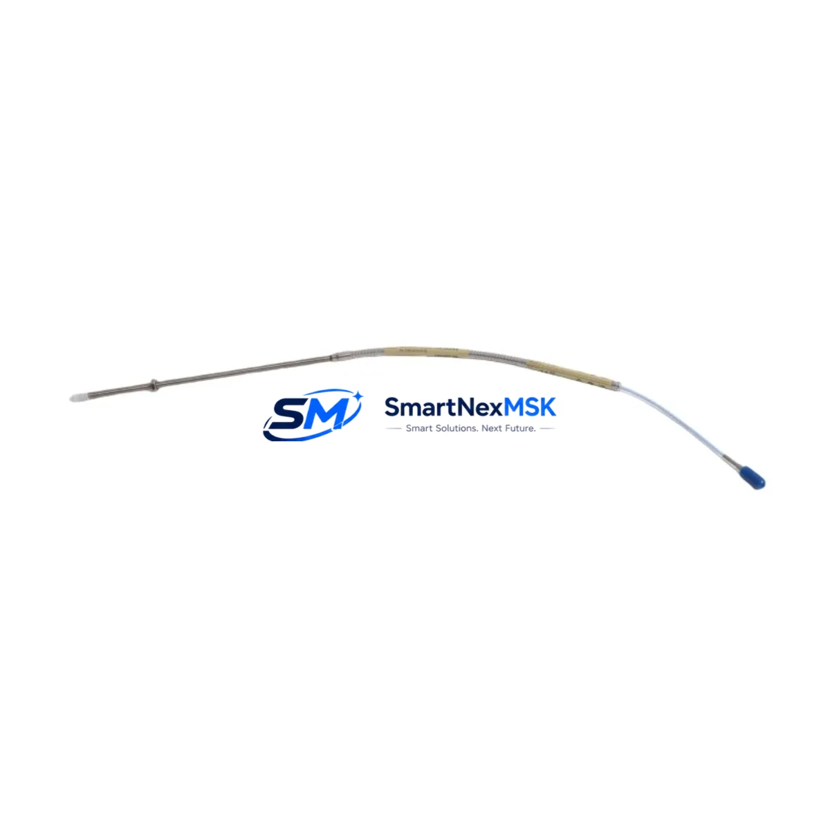
| Probe Type | Eddy Current Proximity Probe, 8mm |
| Cable Length | 2.0 m (standard; see SKU suffix for variants) |
| Sensitivity | 7.87 V/mm (200 mV/mil) nominal |
| Linear Range | 0.25 mm – 2.54 mm (10 – 100 mil) |
| Supply Voltage | –24 VDC (via 3300 XL Proximitor® driver) |
| Operating Temperature | –35°C to +177°C (probe tip) |
| Compatibility | Bently Nevada 3300 XL Proximitor® Sensor (330180 series), 3500 Monitoring System |
| Installation | M10 × 1 thread; standard Bently Nevada mounting hardware |
| Application Environment | Steam turbines, gas turbines, centrifugal compressors, pumps, gearboxes |
| Maintenance Recommendation | Replace probe and extension cable as a matched set; re-gap after installation |
| Origin | USA |
| Warranty | 12 Months — functional performance and manufacturing defects |
Maintenance Planning for Continuous Operation
Replacing the 330902-00-95-02-00 proximity probe in a 3300 XL monitoring loop is rarely an isolated task. A disciplined maintenance engineer will treat this replacement as an opportunity to audit the entire vibration measurement chain and the surrounding control cabinet. Begin by inspecting the matched 330130-080-02-00 extension cable — probe and cable must be replaced as a system-matched pair to preserve calibrated sensitivity. Next, verify the 330180-X1-05 Proximitor® sensor output voltage and gap voltage against the system baseline; a worn Proximitor can mask probe degradation and vice versa.
Within the same control cabinet, check the 3500/15 Power Supply module input voltage and ripple — an unstable DC rail is a common root cause of erratic proximity readings that are misdiagnosed as probe failure. If the system uses a 3500/20 Rack Interface Module, confirm that communication with the DCS or safety system is intact after the probe swap. For installations where the 3300 XL feeds into a 3500/42M Proximitor®/Seismic Monitor, re-verify the channel configuration and alarm setpoints following any hardware change.
During planned outages, extend the inspection to terminal blocks and field wiring in the junction box — corroded or loose terminations are a leading cause of intermittent signal faults. If the machine train includes a 330500 series thrust probe on the same shaft, inspect it concurrently to avoid a second outage. For older installations, consider proactively replacing the 330104 series 5mm probe on auxiliary bearings if it shares the same vintage as the failed 8mm unit. Finally, review the 3300 XL system keyphasor® probe (typically a 330900 series) — a degraded keyphasor signal will corrupt phase-referenced vibration data across all channels and complicate post-maintenance diagnostics.
Site Replacement Workflow
A structured on-site replacement of the 330902-00-95-02-00 minimizes downtime and eliminates re-work. Follow this sequence to ensure system compatibility and signal integrity are maintained throughout:
- Pre-shutdown verification: Document the existing gap voltage (typically –10.0 V to –18.0 V DC) and vibration baseline from the 3500 monitor display or DCS historian before isolating the channel.
- Isolation and de-energization: Inhibit the affected channel in the 3500/42M monitor to prevent spurious trips during probe removal. Confirm the –24 VDC supply to the Proximitor® is isolated at the field junction box.
- Probe removal: Unthread the 330902-00-95-02-00 from the probe holder using the correct spanner. Note the existing gap setting (number of turns from contact) for reference.
- New probe installation: Thread the replacement probe to the same approximate gap, then fine-adjust to achieve the target gap voltage specified in the machine OEM documentation (commonly –10.4 V for mid-range gap on steel targets).
- Cable and connector inspection: Before reconnecting the extension cable, inspect the Belden-compatible coaxial connectors for corrosion, bent pins, or cracked insulation. Replace the extension cable if any anomaly is found.
- System re-energization and verification: Re-energize the Proximitor®, confirm gap voltage is within the linear range, and verify that the 3500 monitor channel displays a clean, stable signal. Compare against the pre-shutdown baseline.
- Alarm reinstatement: Remove the channel inhibit, confirm alert and danger setpoints are active, and log the replacement in the maintenance management system with the new probe serial number.
This workflow applies equally when upgrading from an older 330902 standard series to the 330902-00-95-02-00 XL variant, ensuring backward compatibility with existing Proximitor® drivers and 3500 rack infrastructure without requiring reconfiguration of monitor cards.
Spare Parts Support FAQ
Q1: Is the 330902-00-95-02-00 a direct drop-in replacement for earlier 330902 standard series probes?
Yes. The 330902-00-95-02-00 is designed for backward compatibility within the Bently Nevada 3300 XL ecosystem. It uses the same M10 × 1 thread, the same coaxial connector interface, and the same 7.87 V/mm sensitivity as the standard 330902 series, making it a direct mechanical and electrical replacement. Always verify the target material (steel vs. non-ferrous) and re-gap after installation to confirm the gap voltage falls within the linear range for your specific application.
Q2: Should the extension cable be replaced at the same time as the probe?
Yes, and this is strongly recommended. The 330902-00-95-02-00 probe and its matched extension cable (e.g., 330130-080-02-00) are factory-calibrated as a system. Mixing a new probe with an aged or unmatched cable introduces sensitivity error that can shift vibration readings by several percent — enough to cause nuisance trips or, worse, mask real machinery faults. Replace both components together and re-verify the Proximitor® output voltage after installation.
Q3: What pre-shipment testing is performed on each unit?
Every 330902-00-95-02-00 unit is bench-tested prior to dispatch. Testing includes gap voltage linearity verification across the full 0.25 mm – 2.54 mm linear range, insulation resistance check on the coaxial cable, and connector integrity inspection. Units that do not meet Bently Nevada original specification are rejected. A test report is available upon request for critical applications. All units are covered by a 12-month warranty from the date of shipment.
Q4: How should spare probes be stored to maintain long-term reliability?
Store the 330902-00-95-02-00 in its original packaging in a dry, temperature-controlled environment (10°C – 40°C, <70% RH non-condensing). Avoid storing probes near strong magnetic fields or in areas with high vibration. Inspect the coaxial connector and probe tip for corrosion annually. For long-term strategic spares (12–36 months), consider vacuum-sealed packaging with desiccant. Rotate stock on a first-in, first-out basis to ensure the oldest units are deployed first.
© 2026 SMARTNEXMSK. All rights reserved.
Original Source: https://smartnexmsk.com
Contact: sales@smartnexmsk.com | +86 18259474341


