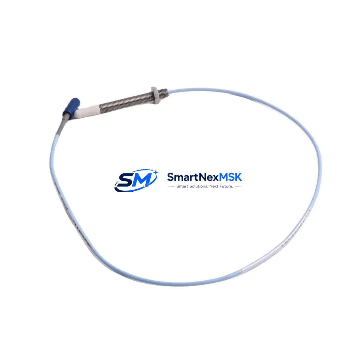
Bently Nevada 330903-00-04-10-02-05/CN Retrofit-Ready Proximitor Extension Cable for 3300 NSv Control Systems
The Bently Nevada 330903-00-04-10-02-05/CN is a field-proven Proximitor Extension Cable engineered for seamless integration into Bently Nevada 3300 NSv Series vibration monitoring systems. As legacy machinery protection platforms approach end-of-life and OEM spare parts become increasingly scarce, this cable assembly provides a direct, specification-matched replacement path that eliminates the need for full system redesign. Whether you are restoring a tripped monitoring loop, upgrading a deteriorated cable run, or migrating from an older 3300 Series rack to a current-generation configuration, the 330903-00-04-10-02-05/CN delivers the signal integrity and mechanical compatibility required for continuous, reliable operation.
This extension cable is designed to bridge the Proximitor/Seismic Monitor sensor head and the 3300 NSv monitor module, maintaining the precise impedance and shielding characteristics that Bently Nevada’s eddy-current proximity measurement chain demands. Signal attenuation, ground loop interference, and connector oxidation are among the most common failure modes in aging cable assemblies — all of which this replacement directly addresses. The cable is compatible with standard 3300 NSv rack configurations and integrates without modification alongside companion modules such as the 3300/16 Dual Proximitor Monitor, the 3300/20 Radial Vibration Monitor, and the 3300/55 Keyphasor Module, preserving existing channel assignments and alarm setpoints.
Upgrade Compatibility Table
| Parameter | Details |
|---|---|
| SKU / Part Number | 330903-00-04-10-02-05/CN |
| Brand | Bently Nevada |
| Compatible Series | Bently Nevada 3300 NSv Vibration Monitoring System |
| Cable Type | Proximitor Extension Cable |
| Connector Interface | Standard Bently Nevada coaxial connector, compatible with 3300 NSv Proximitor/Seismic Monitor inputs |
| Installation Requirement | No rack modification required; direct plug-in replacement |
| Communication Compatibility | Passive signal cable; compatible with all 3300 NSv monitor communication configurations |
| Replacement Recommendation | Direct drop-in replacement for worn, damaged, or discontinued OEM cable assemblies |
| Commissioning Notes | Verify gap voltage at sensor tip post-installation; confirm signal chain continuity before returning loop to service |
| Warranty | 12-Month Warranty — covers manufacturing defects and signal integrity under normal operating conditions |
Retrofit Planning for Existing Automation Systems
Successful integration of the 330903-00-04-10-02-05/CN into an existing machinery protection system requires a structured pre-installation review. Begin by auditing the current cable routing from the proximity probe through the conduit to the 3300 NSv rack. Confirm that the existing 3300/01-01-00-00 Rack Interface Module and the associated 3300 NSv power supply module are delivering stable ±24 VDC to the monitoring chain — voltage fluctuations at the supply rail are a leading cause of false gap voltage readings after cable replacement.
Next, document the current gap voltage reading for each channel before disconnecting the old cable. This baseline, typically between −10 VDC and −18 VDC depending on probe gap, serves as the acceptance criterion for post-installation verification. When routing the new 330903-00-04-10-02-05/CN, maintain physical separation from high-voltage power conductors and variable frequency drive (VFD) output cables to prevent electromagnetic interference from corrupting the low-level proximity signal.
For sites running the System 1 Evolution condition monitoring software or an older System 1 v5.x platform, no software reconfiguration is required — the cable replacement is transparent to the data acquisition layer. However, if the retrofit is part of a broader migration from a legacy 3300 Series rack to a 3500 Series rack, additional steps are necessary: the 3500/42M Proximitor/Seismic Monitor module uses a different connector pinout, and a 3500/92 Communication Gateway Module may be required to maintain Modbus or FOUNDATION Fieldbus connectivity to the plant DCS.
In multi-channel installations, replace cables one channel at a time to preserve monitoring coverage on adjacent channels. Coordinate with the control room to place only the affected channel in bypass mode using the 3300 NSv front-panel bypass switch, rather than taking the entire rack offline. This approach keeps the 3300/16 Dual Proximitor Monitor active on the unaffected channel and maintains alarm annunciation to the plant safety system throughout the procedure.
Where the retrofit involves simultaneous replacement of the proximity probe — for example, substituting a worn 330730-080-00-00 8mm probe assembly — verify that the new probe’s sensitivity factor (mV/mil) matches the calibration stored in the monitor module. A mismatch will shift the gap voltage baseline and may trigger spurious high-vibration alarms. If the site uses a 3300/95 Tachometer Interface Module for speed measurement on the same shaft, confirm that the Keyphasor signal is unaffected by the cable work before releasing the machine to operation.
Downtime Control During System Migration
Minimizing unplanned downtime during a cable replacement or system migration is a primary concern for any rotating machinery application. The 330903-00-04-10-02-05/CN is supplied tested and ready for immediate installation, eliminating the bench-testing step that is often required with unverified surplus parts. Each unit undergoes continuity, insulation resistance, and connector integrity checks prior to shipment, so the field team can proceed directly to installation without additional incoming inspection.
To further compress the maintenance window, prepare the replacement cable, connector tools, and gap-setting gauge before the machine is taken offline. Pre-label the cable with the channel number and target gap voltage to prevent cross-connection errors in multi-probe installations. If the site’s maintenance management system requires a work order closure with as-found and as-left gap voltage records, capture these readings with a calibrated digital voltmeter at the monitor module’s test points — this satisfies most plant documentation requirements without requiring a separate instrument loop check.
For critical applications where even a brief monitoring gap is unacceptable, consider a hot-standby approach: install the new 330903-00-04-10-02-05/CN in parallel with the existing cable before disconnecting the old assembly, verify the gap voltage on the new cable, then transfer the monitor input to the new cable with the machine running. This technique, supported by the 3300 NSv’s channel bypass architecture, allows the cable swap to be completed with zero monitoring downtime. Once the new cable is confirmed in service, remove the old assembly and restore the channel from bypass. The entire procedure typically requires less than 15 minutes per channel when parts and personnel are pre-staged.
Retrofit Support FAQ
Q: Is the 330903-00-04-10-02-05/CN a direct replacement for the original Bently Nevada cable, or are there wiring differences I need to account for?
A: This cable is a specification-matched replacement for the original OEM assembly. Connector type, cable impedance, and shielding configuration are identical to the factory part. No wiring modifications are required at the monitor module or at the probe junction box. Simply disconnect the old cable, route and connect the new assembly, and verify gap voltage at the monitor test points.
Q: Will this cable work if I am migrating from a 3300 Series rack to a 3500 Series rack?
A: The 330903-00-04-10-02-05/CN is designed for 3300 NSv Series applications. If you are migrating to a 3500 Series platform, the 3500/42M monitor module uses a different cable interface. In that scenario, a 3500-compatible extension cable is required. Contact our technical team to confirm the correct part number for your target platform before ordering.
Q: What commissioning checks are required after installation?
A: After installation, measure the gap voltage at the monitor module’s channel test point with the machine stationary. Confirm the reading falls within the probe manufacturer’s specified range (typically −10 VDC to −18 VDC for standard 5mm and 8mm probes). Check for signal noise on the OK relay output and confirm the channel clears the OK threshold. If the site uses System 1 software, verify that the channel is receiving a valid dynamic signal before returning the machine to service.
Q: What does the 12-month warranty cover, and what is the process if a unit fails in service?
A: The 12-month warranty covers manufacturing defects, connector failures, and signal integrity issues arising under normal operating conditions. It does not cover damage resulting from incorrect installation, mechanical abuse, or exposure to environments outside the cable’s rated temperature and chemical resistance specifications. If a warranty claim is required, contact sales@smartnexmsk.com with the order number and a description of the failure mode. Replacement units are dispatched from stock, typically within 2 business days.
© 2026 SMARTNEXMSK. All rights reserved.
Original Source: https://smartnexmsk.com
Contact: sales@smartnexmsk.com | +86 18259474341


