Bently Nevada 330903-00-05-05-01-00 Retrofit-Ready Proximity Transducer for 3300 XL Control Systems
The Bently Nevada 330903-00-05-05-01-00 is a high-precision proximity transducer engineered for seamless integration into legacy 3300 XL NSv vibration monitoring systems. As industrial facilities face increasing pressure to extend the operational life of existing machinery protection infrastructure, this transducer provides a verified drop-in replacement path that eliminates the need for full system overhauls. Whether you are managing a turbine protection panel, a compressor monitoring rack, or a rotating equipment control cabinet, the 330903-00-05-05-01-00 delivers the signal fidelity and mechanical compatibility required for reliable continuous operation.
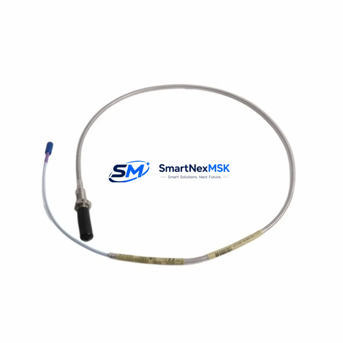
Designed to interface directly with the Bently Nevada 3300 XL series signal conditioning architecture, this transducer maintains the standard 5-metre armored cable assembly, 8 mm tip diameter, and -24 VDC bias voltage output that field engineers depend on during hot-swap replacement procedures. The unit is fully compatible with the 3300 XL 8mm Proximity Transducer System and can be commissioned without reprogramming the host monitor or reconfiguring the Keyphasor module. Facilities running Bently Nevada System 1 software will find that existing trend data, alarm setpoints, and gap voltage calibration records remain valid after substitution.
Before initiating a replacement, engineers should verify the following parameters against the existing installation: gap voltage at the installed position (typically -10 VDC ±0.5 VDC for a standard 3300 XL configuration), cable routing and conduit fill, connector pinout at the 3300 XL proximitor/driver interface, and the shield grounding scheme at the junction box. The 330903-00-05-05-01-00 uses the standard 3-wire coaxial extension cable arrangement compatible with the 330130 series extension cables, ensuring that existing cable runs do not require replacement in most retrofit scenarios.
Upgrade Compatibility Table
| Parameter | 330903-00-05-05-01-00 (This Unit) | Retrofit Notes |
|---|---|---|
| Tip Diameter | 8 mm | Direct fit for standard 3300 XL 8mm probe mounts |
| Cable Length | 5 metres (armored) | Compatible with 330130 extension cable; no re-routing required |
| Bias Voltage Output | -24 VDC nominal | Matches 3300 XL proximitor input specification |
| Sensitivity | 7.87 V/mm (200 mV/mil) | No recalibration of monitor cards required |
| Target Material Compatibility | AISI 4140 steel (standard) | Verify shaft material; non-standard alloys require scale factor adjustment |
| Connector Interface | Standard BNC / coaxial | Direct connection to 3300 XL proximitor driver module |
| Communication Compatibility | Analog signal (4–20 mA via monitor) | Compatible with System 1 software and legacy DCS analog input cards |
| Installation Requirement | Standard probe holder / bracket mount | No mechanical modification required for OEM bracket installations |
| Commissioning | Gap voltage verification at -10 VDC ±0.5 VDC | Use Bently Nevada gap voltage meter or DVM; no special tools required |
| Warranty | 12-Month Warranty — covers manufacturing defects and signal performance under specified operating conditions | |
Retrofit Planning for Existing Automation Systems
Successful integration of the 330903-00-05-05-01-00 into an operating plant environment requires a structured approach to retrofit planning. In most 3300 XL-based machinery protection installations, the transducer works in conjunction with a 3300 XL proximitor/driver module housed in a standard 19-inch rack or DIN-rail enclosure. The proximitor conditions the raw eddy-current signal from the probe and delivers a calibrated DC voltage to the associated 3300 XL monitor card — typically a radial vibration, axial position, or speed monitor depending on the measurement point.
When planning the retrofit, the engineering team should document the current rack layout, including the position of each 3300 XL monitor card, the associated Keyphasor module (model 3300 XL Keyphasor), and any 3300 XL I/O module used for relay output or 4–20 mA retransmission to the plant DCS. If the facility uses a Bently Nevada 3500 series rack in parallel for critical machinery, the replacement transducer must also be verified against the 3500/42M Proximitor I/O Module input specifications to ensure signal compatibility across both monitoring platforms.
Cable management is a critical element of the retrofit. The 330903-00-05-05-01-00 ships with a 5-metre armored cable, which in most installations connects to a 330130-080-00-00 or equivalent extension cable running back to the proximitor in the control room or local junction box. Engineers should inspect the extension cable for insulation degradation, connector corrosion, and shield continuity before reusing it with the new transducer. If the extension cable requires replacement, the 330130 series is the recommended compatible option and can be ordered in standard lengths to match the existing cable run.
For facilities migrating from older Bently Nevada 7200 series or 9000 series transducer systems to the 3300 XL platform, additional interface considerations apply. The 7200 series used a different sensitivity specification and connector standard, so a direct cable reuse is not possible. In these cases, the retrofit scope typically includes replacement of the proximitor driver, extension cable, and junction box terminations in addition to the probe itself. The 3300 XL system’s improved signal-to-noise ratio and tighter temperature compensation make this migration worthwhile for facilities seeking to reduce nuisance trips and improve vibration trend accuracy.
Power supply capacity in the control cabinet should also be reviewed. The 3300 XL proximitor requires a regulated -24 VDC supply, typically sourced from a dedicated Bently Nevada power supply module or a plant-standard 24 VDC rail with appropriate polarity inversion. If the existing power supply is shared with other instrumentation — such as 4–20 mA transmitters, solenoid valve drivers, or HMI panel backlights — the engineer should verify that the available current budget accommodates the additional transducer load without causing supply voltage droop that could affect measurement accuracy.
Downtime Control During System Migration
Minimizing unplanned downtime is the primary operational constraint in any machinery protection system retrofit. For the 330903-00-05-05-01-00 replacement, the recommended approach is to pre-stage the new transducer, extension cable, and any required mounting hardware before the scheduled maintenance window. All gap voltage measurements should be performed on the bench using a calibrated gap voltage simulator before the unit is installed in the field, confirming that the transducer’s output characteristic matches the expected -10 VDC gap voltage at the nominal installation gap.
During the replacement window, the associated 3300 XL monitor channel should be placed in bypass mode using the System 1 software or the front-panel bypass switch on the monitor card. This prevents spurious alarms or relay trips during the physical swap. The original program logic in the DCS — including any interlock sequences that reference the vibration measurement point — should be documented and verified against the post-replacement signal before the bypass is removed. If the facility uses a Yokogawa, Emerson DeltaV, or Honeywell Experion DCS, the analog input card receiving the 4–20 mA retransmission signal should be checked for correct scaling after the new transducer is commissioned.
HMI faceplate displays referencing the affected measurement point should be reviewed to confirm that the engineering unit scaling, alarm limits, and trend history are correctly associated with the new transducer’s signal. In most System 1 configurations, the measurement point database entry does not require modification if the replacement transducer uses the same sensitivity and gap voltage specification as the original unit. Field commissioning should conclude with a full functional test: rotate the shaft by hand or use a calibrated target to verify that the vibration reading on the monitor card and the DCS display are consistent and within the expected range before returning the machine to service.
Retrofit Support FAQ
Q: Is the 330903-00-05-05-01-00 a direct replacement for the original Bently Nevada 3300 XL 8mm proximity transducer?
A: Yes. The 330903-00-05-05-01-00 is dimensionally and electrically compatible with the standard 3300 XL 8mm proximity transducer system. It uses the same tip diameter, cable assembly standard, bias voltage, and sensitivity specification, allowing direct substitution without modification to the proximitor, monitor card, or extension cable in most installations.
Q: What commissioning steps are required after installation?
A: After physical installation, verify the gap voltage at the probe tip using a digital voltmeter or Bently Nevada gap voltage meter. The nominal gap voltage should read -10 VDC ±0.5 VDC at the standard installation gap for 3300 XL 8mm systems. Confirm the vibration reading on the associated monitor card is stable and within the expected range before removing the channel bypass and returning the machine to normal monitoring.
Q: Can this transducer be used with a Bently Nevada 3500 series rack?
A: The 330903-00-05-05-01-00 is designed for the 3300 XL system. While the electrical signal characteristics are similar to those used in 3500 series installations, compatibility with the 3500/42M Proximitor I/O Module should be verified against the specific rack configuration and I/O module firmware version before installation in a 3500 series rack.
Q: What does the 12-month warranty cover?
A: The 12-month warranty covers manufacturing defects and signal performance deviations under the specified operating conditions defined in the Bently Nevada 3300 XL transducer datasheet. Warranty claims require the unit to be returned with documentation of the installation configuration and the observed fault condition. Units showing evidence of mechanical damage, incorrect installation gap, or operation outside the specified temperature and cable length limits are not covered under the standard warranty terms.
© 2026 SMARTNEXMSK. All rights reserved.
Original Source: https://smartnexmsk.com
Contact: sales@smartnexmsk.com | +86 18259474341


