Bently Nevada 330903-00-06-05-01-00 3300 XL NSv Spare: Spare Replacement & Industrial Downtime Risk Control
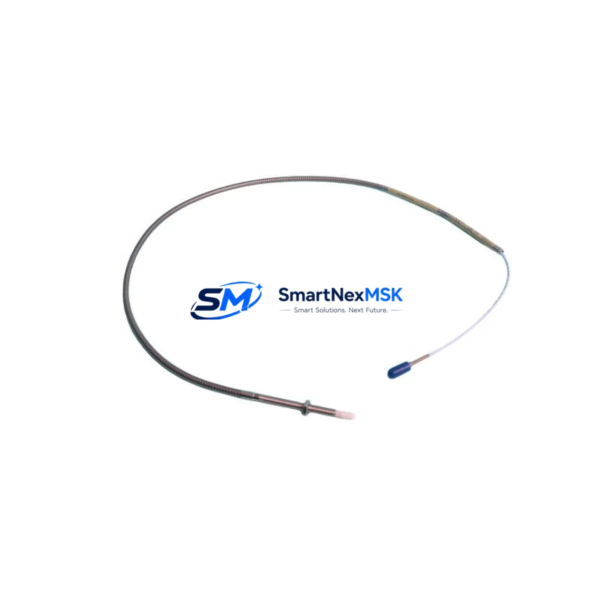
The Bently Nevada 330903-00-06-05-01-00 is a precision proximity transducer system designed for the 3300 XL NSv series, widely deployed in rotating machinery protection systems across power generation, oil & gas, petrochemical, and heavy industrial facilities. As a maintenance-ready original spare, this unit supports rapid field replacement to minimize unplanned downtime and restore continuous monitoring capability to critical machinery trains.
Maintenance engineers and procurement teams managing aging 3300 XL NSv installations rely on verified original spare parts to maintain system integrity. The 330903-00-06-05-01-00 is a direct-fit replacement for its series, preserving calibration traceability, signal chain accuracy, and compliance with API 670 machinery protection standards. Each unit is tested prior to dispatch and backed by a 12-month warranty, ensuring confidence in long-term spare parts supply.
Whether you are executing a planned outage, responding to a transducer fault alarm, or building a strategic spare parts inventory for a turbine or compressor train, the 330903-00-06-05-01-00 provides the reliability and compatibility assurance required for industrial-grade maintenance operations.
Spare Maintenance Table
| Parameter | Specification |
|---|---|
| Part Number / SKU | 330903-00-06-05-01-00 |
| Brand | Bently Nevada |
| Series | 3300 XL NSv Proximity Transducer System |
| Product Type | Proximity Transducer System |
| Output Signal | -18 VDC nominal (standard Bently Nevada proximity output) |
| Cable Length | 6 m (extension cable configuration per SKU suffix) |
| Target Material Compatibility | Steel (AISI 4140 / 4340 per API 670) |
| Operating Temperature | -35°C to +85°C (probe); -35°C to +66°C (driver) |
| Ingress Protection | IP67 (probe assembly) |
| Compliance | API 670, CE, ATEX (zone classification per installation) |
| Mounting Thread | M10 x 1 (standard 3300 XL series) |
| Application | Radial vibration, axial position, speed measurement on rotating machinery |
| Compatibility | 3300 XL NSv monitors, 3500 series rack (with adapter), System 1 software |
| Condition | Original, new or reconditioned — tested and verified before dispatch |
| Warranty | 12 Months from date of shipment |
| Lead Time | In-stock: ships within 3–5 business days; ex-stock available |
| Origin | USA (Bently Nevada / Baker Hughes) |
Maintenance Planning for Continuous Operation
When replacing the 330903-00-06-05-01-00 proximity transducer system during a planned or emergency maintenance event, a thorough inspection of the surrounding signal chain and power infrastructure is essential to prevent repeat failures and ensure system readiness after restart.
Begin by verifying the 3300 XL NSv driver/monitor module seated in the rack — a faulty transducer can mask underlying driver degradation, and replacing the probe without checking the driver may result in persistent alarm conditions. Inspect the 3300 XL 16-channel monitor or equivalent rack card for any indication of channel faults, power supply irregularities, or communication errors logged in System 1.
Check the extension cable assembly (typically a 330130 or 330180 series cable) for insulation damage, connector corrosion, or continuity loss — cable degradation is a leading cause of transducer system faults in high-vibration environments. Inspect the proximitor sensor housing for mechanical damage, thread wear, or contamination that could affect gap setting accuracy.
Review the rack power supply module (such as the 3500/15 or equivalent) for output voltage stability; proximity transducer systems are sensitive to supply voltage fluctuations. Confirm that the terminal block and field wiring connections within the control cabinet are tight, correctly labeled, and free from oxidation — loose connections at the I/O termination point are a common source of intermittent signal faults.
If the installation includes a Keyphasor module (e.g., 3500/25 or 330980 series), verify its gap and output signal as part of the same maintenance window, since Keyphasor reference signals are critical for phase-referenced vibration analysis. For facilities running System 1 Evolution or System 1 Condition Monitoring Software, confirm that the replacement transducer is re-commissioned and its channel configuration matches the original calibration record.
Where the control cabinet also houses 4–20 mA signal isolators or Zener barriers for hazardous area installations, inspect these components for drift or degradation as part of the same outage. Finally, review the grounding and shielding continuity of the transducer cable run — improper shielding is a frequent source of noise-induced false alarms in proximity measurement systems.
Site Replacement Workflow
Step 1 — Pre-replacement verification: Confirm the replacement SKU 330903-00-06-05-01-00 matches the installed configuration by cross-referencing the suffix codes (cable length, connector type, driver compatibility). Retrieve the original calibration certificate if available.
Step 2 — Safe isolation: Follow site LOTO (Lockout/Tagout) procedures. Inhibit the monitor channel in System 1 or the 3300/3500 rack to prevent spurious trips during replacement. Document the pre-removal gap voltage reading.
Step 3 — Physical replacement: Remove the probe assembly carefully, noting the installed gap distance (typically 1.0–2.5 mm for standard steel targets). Install the new 330903-00-06-05-01-00 unit, set the gap per the calibration specification, and torque the locknut to the manufacturer’s specification.
Step 4 — Signal verification: With the driver powered, measure the output voltage at the monitor input terminals. Confirm the DC gap voltage is within the linear range (typically -10 to -18 VDC). Check for noise or signal instability before re-enabling the monitor channel.
Step 5 — System recommission: Re-enable the channel in System 1, clear inhibits, and confirm alarm setpoints are active. Log the replacement in the maintenance management system (CMMS) with the new serial number and calibration date.
This workflow minimizes restart risk, maintains API 670 compliance, and ensures the replacement is fully documented for audit and lifecycle tracking purposes.
Spare Parts Support FAQ
Q1: Is the 330903-00-06-05-01-00 compatible with both 3300 XL and 3500 series monitors?
The 330903-00-06-05-01-00 is natively designed for the 3300 XL NSv series. Compatibility with 3500 series monitors depends on the specific monitor card and may require an adapter or configuration change. We recommend confirming the target monitor model before ordering. Our technical team can assist with compatibility verification.
Q2: What does the 12-month warranty cover?
The 12-month warranty covers manufacturing defects, signal output failures, and mechanical integrity of the probe and connector assembly under normal operating conditions. It does not cover damage resulting from improper installation, incorrect gap setting, or operation outside specified environmental limits. Warranty claims are supported with a replacement or repair at no additional cost.
Q3: How do you verify the unit before shipment?
Each 330903-00-06-05-01-00 unit undergoes pre-shipment functional testing including output voltage verification, insulation resistance check, and connector integrity inspection. A test report is available upon request. Units are packaged in anti-static, shock-protected packaging to maintain condition during transit.
Q4: Can you support long-term or blanket spare parts orders for fleet maintenance programs?
Yes. We support scheduled spare parts supply agreements for facilities managing multiple machinery trains or multi-site operations. Long-term supply arrangements can include reserved stock, priority lead times, and consolidated documentation packages. Contact our team to discuss your maintenance program requirements.
© 2026 SMARTNEXMSK. All rights reserved.
Original Source: https://smartnexmsk.com
Contact: sales@smartnexmsk.com | +86 18259474341


