Bently Nevada 330903-00-09-10-02-05/CN Spare 3300 NSv: Proximity Probe Extension Cable for Industrial Downtime Recovery
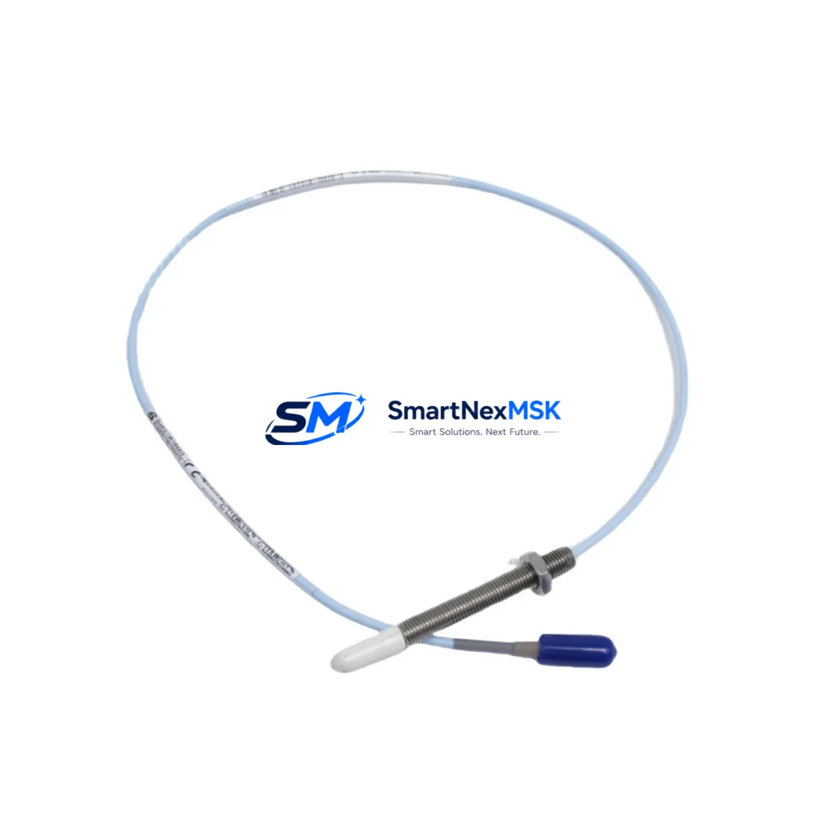
The Bently Nevada 330903-00-09-10-02-05/CN is an original proximity probe extension cable engineered for the 3300 NSv series vibration monitoring system. Designed to bridge the gap between the proximity probe and the proximitor/driver module, this cable is a critical link in continuous machinery protection circuits found in turbines, compressors, pumps, and rotating equipment across oil & gas, power generation, and heavy manufacturing facilities. When this cable degrades, becomes intermittent, or fails outright, the entire vibration channel is compromised — triggering false alarms, masking real faults, or causing unplanned shutdowns. Stocking a verified replacement is the first line of defense against unscheduled downtime.
This cable is rated for the 3300/16 and 3300/25 monitor configurations and is fully compatible with the standard Bently Nevada 3300 NSv proximitor driver. It maintains the precise signal conditioning path required for eddy-current proximity measurements, ensuring that gap voltage, direct voltage, and dynamic vibration signals are transmitted without attenuation or noise injection. Maintenance engineers working on legacy Bently Nevada installations will recognize this part number as a direct, drop-in replacement that requires no recalibration of the proximitor or monitor card when the cable length and connector type are matched correctly.
Spare Maintenance Table
| Parameter | Specification |
|---|---|
| Part Number / SKU | 330903-00-09-10-02-05/CN |
| Brand | Bently Nevada |
| Series | 3300 NSv Proximity System |
| Product Type | Proximity Probe Extension Cable |
| Cable Length | 9 m (per SKU segment encoding) |
| Connector Type | Standard Bently Nevada coaxial MIL-spec connectors |
| Compatible Monitors | 3300/16, 3300/25, 3300 NSv series |
| Compatible Proximitors | 3300 XL 8mm, 3300 NSv Proximitor/Driver |
| Signal Type | Eddy-current proximity (gap voltage, direct voltage, dynamic) |
| Operating Temperature | -40°C to +85°C (cable); per Bently Nevada 3300 NSv spec |
| Installation Environment | Industrial: turbine bearing housings, compressor skids, pump pedestals |
| Origin | USA (Bently Nevada / Baker Hughes) |
| Condition | Original spare — new or factory-refurbished |
| Warranty | 12 months from date of shipment |
| Pre-shipment Testing | Continuity, insulation resistance, and connector integrity verified |
| Maintenance Recommendation | Replace at first sign of intermittent gap voltage, inspect connectors annually |
Maintenance Planning for Continuous Operation
A proximity probe extension cable failure rarely occurs in isolation. When a maintenance engineer identifies a degraded or open 330903-00-09-10-02-05/CN cable, the surrounding components in the same vibration channel and control cabinet should be inspected simultaneously to prevent repeat call-outs and to maximize the value of each planned outage window.
Start at the probe end: the Bently Nevada 330103-00-08-10-02-05 proximity probe (or equivalent 8 mm probe in the 330100 series) should be checked for tip damage, contamination, and correct gap setting — typically 1.0 to 1.5 mm for most rotating equipment applications. A worn probe combined with a new cable will still produce erratic readings. Moving toward the proximitor, verify the Bently Nevada 3300 XL 8mm Proximitor/Driver output voltage at the OK relay terminals; a healthy proximitor should hold the OK relay closed within the linear range. If the proximitor has accumulated more than 10 years of service, consider stocking a spare 3300/20-02-01-00 or equivalent proximitor module alongside the cable.
At the monitor rack level, inspect the Bently Nevada 3300/16 or 3300/25 monitor card for alarm setpoint drift, relay contact wear, and firmware revision. These cards communicate over the TDI (Transient Data Interface) or System 1 network; confirm that the communication module — often a 3500/92 or 3300 TDI gateway — is logging data correctly after the cable swap. A cable replacement that is not followed by a channel verification in System 1 can leave a latent fault undetected.
In the same control cabinet, check the 24 VDC power supply module feeding the proximitor rail. Voltage sag or ripple on the proximitor supply is a common root cause of nuisance OK relay trips that are misdiagnosed as cable faults. Inspect terminal blocks and cable shields for corrosion, particularly in humid or offshore environments. Phoenix Contact or Weidmüller terminal blocks used in Bently Nevada junction boxes should be torqued to spec and re-inspected after any cable pull. If the installation uses a signal isolator or barrier between the proximitor and the DCS analog input card, verify that the isolator’s input impedance is within the proximitor’s drive capability — a mismatched galvanic isolator can attenuate the vibration signal and cause false high-vibration alarms even with a new cable installed.
For facilities running a Bently Nevada 3500 series rack alongside legacy 3300 NSv hardware, this is also an appropriate time to audit the 3500/42M position monitor or 3500/40M proximitor monitor channels that share the same machinery protection philosophy. Spare cables, probes, and proximitors for both platforms should be held in the same spare parts kit to avoid split procurement lead times during an emergency.
Site Replacement Workflow
Step 1 — Isolation and permit: Obtain a hot-work or electrical isolation permit as required by site procedures. Note the current gap voltage reading from the System 1 or local monitor display before disconnecting — this is your baseline for post-installation verification.
Step 2 — Cable removal: Disconnect the extension cable at both the probe junction and the proximitor input. Inspect the coaxial connectors on the old cable for moisture ingress, pin damage, or corrosion. Document findings for the maintenance record.
Step 3 — New cable installation: Route the 330903-00-09-10-02-05/CN replacement cable following the original cable path. Avoid sharp bends below the minimum bend radius. Secure with cable ties at the same intervals as the original. Torque connectors finger-tight plus one-quarter turn — do not over-torque coaxial connectors.
Step 4 — Gap verification: Power up the proximitor and measure gap voltage at the proximitor output terminals. Compare against the pre-removal baseline. Adjust probe gap if the reading deviates by more than ±0.5 VDC from the expected value for the installed shaft material and probe type.
Step 5 — Channel functional test: Confirm OK relay status, alarm relay status, and dynamic signal quality in System 1 or the local monitor display. Log the post-replacement gap voltage, direct voltage, and noise floor in the maintenance management system (CMMS). Return the machine to service only after all channels show healthy status.
This workflow is applicable whether replacing a failed cable on an emergency basis or executing a planned cable replacement during a scheduled turnaround. The same procedure applies when upgrading from an older 330900 series cable to the current 330903 series, which offers improved connector sealing and shielding for high-EMI environments.
Spare Parts Support FAQ
Q1: Is the 330903-00-09-10-02-05/CN compatible with both the 3300/16 and 3300/25 monitors?
Yes. This extension cable is designed for the 3300 NSv proximity system and is compatible with the 3300/16 single-channel and 3300/25 dual-channel monitor configurations. Always verify the cable length and connector type match your installed system before ordering.
Q2: How is the cable tested before shipment?
Each unit undergoes continuity testing, insulation resistance measurement, and connector integrity inspection prior to dispatch. A test report is available upon request. The 12-month warranty covers defects in materials and workmanship from the date of shipment.
Q3: Can this cable replace older 330900 series extension cables?
In most cases, yes — the 330903 series is the current production replacement for legacy 330900 series cables of the same length and connector configuration. Confirm the length code in the part number (positions 4–5) matches your installed cable length before substituting. If in doubt, contact our technical team with your existing part number for cross-reference confirmation.
Q4: What is the recommended spare parts inventory strategy for this cable?
For critical rotating equipment (turbines, compressors, main pumps), we recommend holding a minimum of one spare cable per monitored shaft, plus one additional cable per machine train as a buffer. For facilities with 10 or more Bently Nevada channels, a consolidated spare parts kit covering cables, probes, and proximitors reduces emergency procurement lead times from weeks to hours. Long-term supply agreements are available for OEM and EPC customers requiring guaranteed stock allocation.
© 2026 SMARTNEXMSK. All rights reserved.
Original Source: https://smartnexmsk.com
Contact: sales@smartnexmsk.com | +86 18259474341


