Bently Nevada 330903-00-10-05-01-00 Retrofit-Ready Proximity Transducer for 3300 XL NSv Control Systems
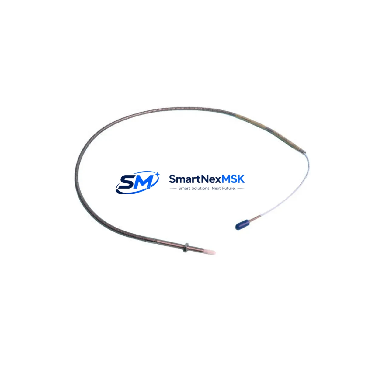
The Bently Nevada 330903-00-10-05-01-00 is a 10 mm eddy current proximity transducer engineered for the 3300 XL NSv monitoring platform. As legacy vibration monitoring systems reach end-of-life or become increasingly difficult to source, this module serves as a verified drop-in replacement for discontinued 3300 Series transducers, enabling plant engineers to restore full shaft-proximity monitoring capability without redesigning the existing signal chain. With a 5-metre integral cable, a sensitivity of 7.87 V/mm, and a linear range of 0.25–2.25 mm, the 330903-00-10-05-01-00 meets the original OEM specification and is compatible with the 3300 XL 8-mm and 3300 XL NSv proximitor/seismic monitors.
For facilities operating rotating machinery — turbines, compressors, pumps, and gearboxes — where the original Bently Nevada 330900 or 330780 series transducers have been discontinued or are no longer available through authorised channels, the 330903-00-10-05-01-00 provides a technically equivalent upgrade path. Engineers replacing a 330780-50-00 or 330900-70-05-01-05-00 will find that terminal wiring, shield grounding, and proximitor driver compatibility are preserved, minimising field rework and reducing the risk of introducing measurement error during changeover.
Upgrade Compatibility Table
| Parameter | Detail |
|---|---|
| SKU / Part Number | 330903-00-10-05-01-00 |
| Compatible Monitor | Bently Nevada 3300 XL NSv Proximitor/Seismic Monitor |
| Replaces / Supersedes | 330780-50-00, 330900-70-05-01-05-00, 330903-00-10-05-02-00 |
| Sensing Range | 10 mm (linear range 0.25–2.25 mm) |
| Cable Length | 5 m integral armoured cable |
| Sensitivity | 7.87 V/mm (200 mV/mil) |
| Supply Voltage | −24 VDC (from proximitor driver) |
| Connector / Interface | 3-pin MIL-C-5015 bayonet, compatible with 3300 XL NSv proximitor input |
| Installation | M10 × 1 threaded body; direct replacement, no bracket modification required |
| Communication Compatibility | Analogue 4–20 mA / voltage output; compatible with System 1 and TDXnet data acquisition |
| Commissioning Note | Gap voltage must be re-verified at installation; target −10.0 VDC ± 0.5 V at nominal gap |
| Warranty | 12 months from date of shipment |
Retrofit Planning for Existing Automation Systems
A successful retrofit of the 330903-00-10-05-01-00 into an operating plant begins well before the maintenance window opens. The first step is to audit the existing 3300 XL NSv rack configuration: confirm the proximitor driver card — typically a 3300 XL 8-mm Proximitor/Seismic Monitor or a 3300 XL 16-mm variant — is in serviceable condition and that its internal oscillator circuit is within calibration. If the proximitor card itself is suspect, a parallel replacement using a 3300/16-04-01-01-00-00 or 3300/20-02-01-00-00-00 monitor module should be planned concurrently to avoid a second outage.
Terminal wiring for the 330903-00-10-05-01-00 follows the standard Bently Nevada three-wire convention: centre conductor (signal), shield (common), and outer jacket drain. When replacing a 330780 series transducer, verify that the existing junction box — often a 3300 XL field wiring termination assembly — uses the same pin-out. If the plant uses a 3500/42M Proximitor/Seismic Monitor rack card rather than the standalone 3300 XL NSv chassis, confirm that the driver sensitivity setting matches the 7.87 V/mm output of this transducer; a mismatch will produce a false gap alarm or a buffered output offset that propagates into the System 1 historian.
For facilities that have migrated vibration data acquisition to a 3500 Series rack, the 330903-00-10-05-01-00 remains electrically compatible with the 3500/42M and 3500/44M monitor cards, provided the extension cable — such as a 330130-080-00-00 or 330130-045-00-00 — is rated for the total cable capacitance budget. Where cable runs exceed the standard 5 m integral length, an extension cable must be selected to keep total capacitance within the proximitor specification. The 3300 XL NSv proximitor driver will flag an open-circuit or over-range condition if total cable capacitance exceeds the design limit, so this calculation should be completed during the pre-outage engineering review.
I/O mapping is another critical checkpoint. If the plant’s DCS — whether a Honeywell Experion PKS, an Emerson DeltaV, or an ABB 800xA — receives the 4–20 mA vibration signal from the 3300 XL NSv rack, the engineering unit scaling in the DCS I/O module must be confirmed against the new transducer’s output range. A change in gap voltage offset between the old and new transducer can shift the 4–20 mA zero point by several micrometres, which will appear as a baseline drift in the historian trend and may trigger a spurious alert in the condition monitoring software. Update the DCS tag descriptor and the System 1 channel configuration before returning the machine to service.
Where the plant uses a Bently Nevada 3500/92 communication gateway or a TDXnet Ethernet module for remote monitoring, no protocol changes are required: the 330903-00-10-05-01-00 is transparent to the data acquisition layer. However, if the retrofit is part of a broader migration from the 3300 Series standalone chassis to a 3500 Series rack-based architecture, the opportunity should be taken to review the rack power supply — a 3500/15 Power Supply module — and the rack termination board to ensure they are rated for the expanded I/O count. A 3500/20 Rack Interface Module firmware update may also be required if the rack has not been serviced recently.
Downtime Control During System Migration
Minimising unplanned downtime during a proximity transducer replacement requires a structured hot-swap protocol. Where the process permits, the 3300 XL NSv monitor can be placed in bypass mode — using the front-panel inhibit function or a System 1 software bypass — so that the vibration channel does not trigger a machine trip during the physical transducer swap. This preserves the original control logic in the PLC or safety system without requiring a program download or a safety function proof test.
Before removing the old transducer, record the buffered output voltage at the proximitor BNC connector. This reading — typically between −9.5 V and −10.5 V at nominal gap — serves as the baseline for verifying that the replacement 330903-00-10-05-01-00 is correctly gapped after installation. Once the new transducer is threaded into the bearing housing and the locknut is torqued to specification, adjust the axial position until the buffered output returns to within ±0.2 V of the recorded baseline. Only then should the monitor bypass be released and the channel returned to active protection.
If the machine cannot be taken offline, a temporary parallel monitoring arrangement using a portable data collector — such as a CSI 2140 or a Bently Nevada SCOUT 100 — can be deployed to maintain vibration surveillance on the affected bearing while the permanent transducer is replaced. This approach is particularly valuable in continuous-process industries where a single compressor or pump train supports an entire production unit and a cold shutdown is not operationally feasible.
All replacement units supplied by SMARTNEXMSK are function-tested prior to shipment: gap voltage, sensitivity, and cable continuity are verified against the OEM specification. A test certificate is included with each unit. The 12-month warranty covers manufacturing defects and out-of-specification performance; it does not cover damage resulting from incorrect installation gap, over-voltage on the signal line, or mechanical impact.
Retrofit Support FAQ
Q1: Is the 330903-00-10-05-01-00 a direct replacement for the 330780-50-00?
Yes. The 330903-00-10-05-01-00 supersedes the 330780-50-00 in the Bently Nevada product family. Both use the same M10 × 1 threaded body, the same 3-pin MIL-C-5015 connector, and the same 7.87 V/mm sensitivity. The only practical difference is the integral cable jacket colour and the updated part number label. No wiring changes are required at the junction box or the proximitor driver card.
Q2: What gap voltage should I target during commissioning?
The nominal installation gap for a 10 mm transducer on a steel target is 1.0 mm, which corresponds to a buffered output of approximately −10.0 VDC. Adjust the transducer axial position until the proximitor BNC output reads between −9.5 V and −10.5 V with the shaft stationary at the normal operating position. Record this value in the maintenance management system as the new baseline for alarm setpoint verification.
Q3: Can this transducer be used with a 3500 Series rack instead of the 3300 XL NSv chassis?
Yes, with qualification. The 330903-00-10-05-01-00 is electrically compatible with the 3500/42M and 3500/44M Proximitor/Seismic Monitor cards. Confirm that the total cable capacitance — integral cable plus any extension cable such as a 330130-080-00-00 — remains within the proximitor driver specification. Also verify that the 3500 rack’s channel sensitivity setting is configured for 200 mV/mil (7.87 V/mm) before releasing the channel to active protection.
Q4: What does the 12-month warranty cover, and how is a warranty claim initiated?
The 12-month warranty covers manufacturing defects and out-of-specification sensitivity or gap voltage performance as measured against the Bently Nevada OEM datasheet. To initiate a claim, contact SMARTNEXMSK with the unit serial number, the date of installation, and a description of the observed fault. Units must be returned in original packaging with the test certificate. Warranty does not cover damage from incorrect installation gap, reverse polarity, mechanical impact, or use outside the rated temperature range (−35 °C to +121 °C).
© 2026 SMARTNEXMSK. All rights reserved.
Original Source: https://smartnexmsk.com
Contact: sales@smartnexmsk.com | +86 18259474341


