Bently Nevada 330903-00-10-10-02-05/CN: Retrofit-Ready Proximity Extension Cable for 3300 NSv Control Systems
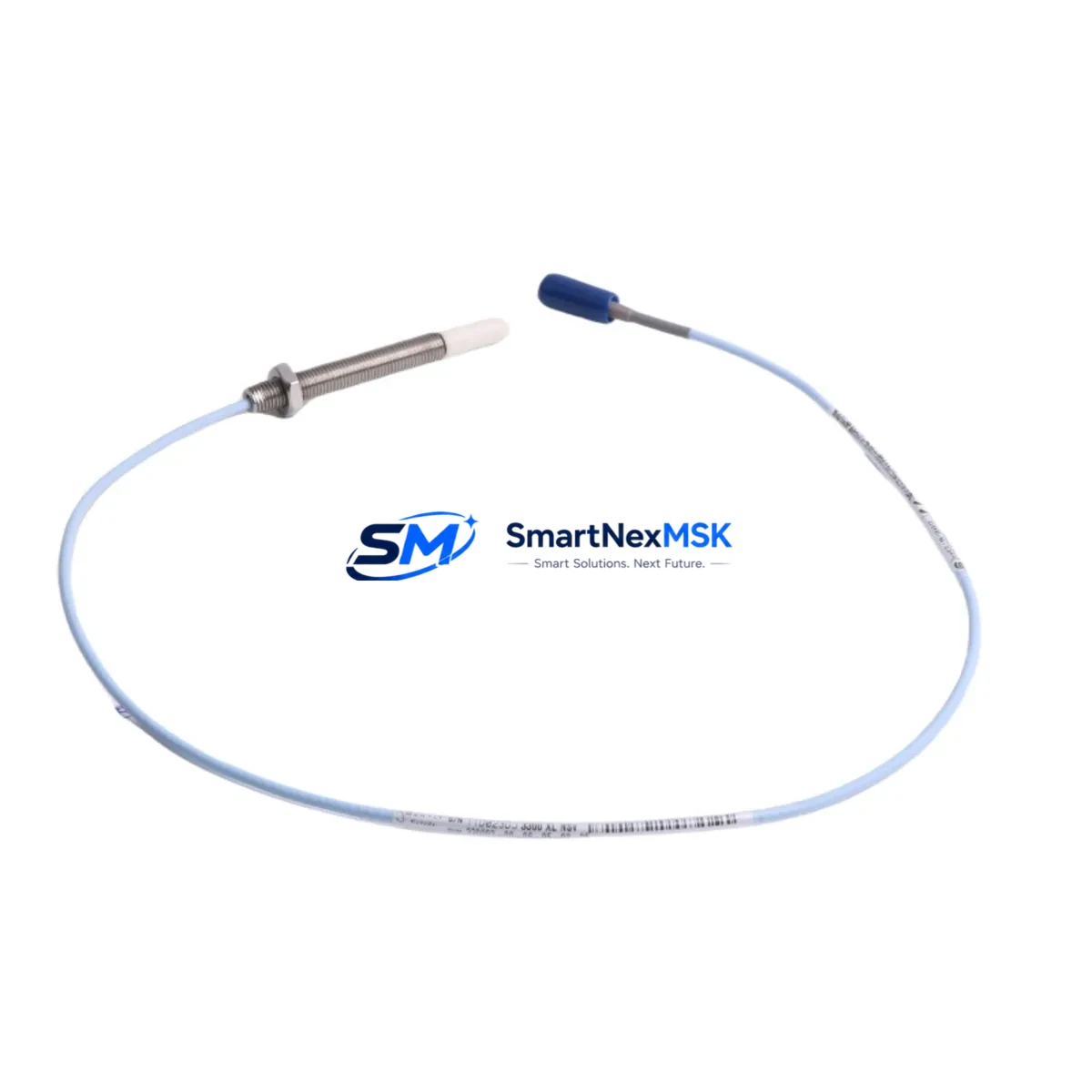
The Bently Nevada 330903-00-10-10-02-05/CN is a 1-meter armored proximity extension cable engineered for the 3300 NSv Series vibration monitoring system. As legacy rotating machinery protection systems reach end-of-life or require spare-part replenishment, this cable serves as a verified drop-in replacement for discontinued or hard-to-source variants within the 3300 NSv platform. Whether you are executing a planned outage upgrade, restoring a tripped monitoring channel, or modernizing a turbine protection cabinet, the 330903-00-10-10-02-05/CN delivers the signal integrity and mechanical compatibility required to maintain continuous machinery protection without reengineering the existing installation.
Sourced from verified supply channels and pre-tested prior to shipment, each unit is backed by a 12-month warranty covering manufacturing defects and signal performance. Stock is maintained to support urgent replacement scenarios, minimizing procurement lead time during unplanned shutdowns.
Upgrade Compatibility Table
| Parameter | Details |
|---|---|
| SKU / Part Number | 330903-00-10-10-02-05/CN |
| Series Compatibility | Bently Nevada 3300 NSv Vibration Monitoring System |
| Cable Length | 1.0 m (extension cable segment) |
| Connector Interface | Standard 3300 NSv coaxial connector — mates directly with 3300 NSv proximitor/driver and field-side junction |
| Installation Requirement | No bracket modification required; direct swap with existing cable routing |
| Communication / Signal Type | Eddy-current proximity signal (passive cable — no active electronics) |
| Replacement Recommendation | Direct replacement for worn, damaged, or discontinued 330903-series extension cables in 3300 NSv channels |
| Commissioning Notes | Verify gap voltage at proximitor output after installation; confirm signal within –10 VDC ± 1 VDC at nominal gap |
| Warranty | 12 months from date of shipment — covers manufacturing defects and signal performance |
Retrofit Planning for Existing Automation Systems
Replacing a proximity extension cable in an operating turbine or compressor protection system requires careful coordination across multiple components. The 330903-00-10-10-02-05/CN interfaces directly with the 3300 NSv proximitor driver module — typically a 330180-51-05 or equivalent driver — mounted in the 3300 NSv rack. Before pulling the existing cable, engineers should confirm that the associated 3300 NSv monitor module (such as the 3300/16 or 3300/20 dual-channel vibration monitor) is in bypass or inhibit mode to prevent a spurious trip during the swap.
On the field side, the cable terminates at the proximity probe — commonly a 330101 or 330105 series 8 mm probe — installed in the bearing housing. Technicians should inspect the probe tip clearance and confirm the probe body has not migrated before reconnecting the new extension cable. The complete measurement loop — probe, extension cable, and proximitor — must be treated as a matched system: cable length directly affects the system scale factor, so substituting a non-matched length will shift the output voltage and require recalibration of the 3300 NSv monitor’s gap and scale settings.
Within the control cabinet, the 3300 NSv rack typically shares a backplane with other condition monitoring modules, including temperature monitors, thrust position monitors, and speed monitors. During a cable replacement outage, it is common practice to also inspect the rack power supply module — such as the 3300/05 power supply — and verify that DC bus voltage is stable before returning the channel to service. If the plant is simultaneously upgrading from an older 3500 series rack to the 3300 NSv platform, the cable replacement is an ideal time to audit all field wiring terminations at the junction box and update the as-built drawings.
For facilities running a DCS or safety instrumented system (SIS) that receives 4–20 mA or relay outputs from the 3300 NSv monitors, the retrofit team should confirm that the DCS input card — often a Yokogawa, Emerson DeltaV, or Honeywell Experion analog input module — continues to receive valid signals after the cable swap. Any gap in signal continuity may trigger a process alarm or SIS action, so coordination with the control room operator is essential before and after the replacement.
If the plant’s CMMS or historian (such as OSIsoft PI or AspenTech) is logging vibration trend data from the 3300 NSv system, the maintenance team should note the timestamp of the cable replacement and verify that post-replacement vibration readings fall within the established baseline band. Anomalous readings immediately after installation typically indicate a gap voltage error or a loose connector at the proximitor input — both of which are resolved by re-seating the cable connector and re-checking the gap.
Downtime Control During System Migration
Minimizing downtime during a proximity cable replacement begins with pre-staging. Before the outage window opens, the replacement 330903-00-10-10-02-05/CN cable should be on-site, inspected, and confirmed against the channel’s existing cable length and connector type. The 3300 NSv monitor channel should be placed in inhibit mode — using the front-panel keypad or the System 1 software interface — so that the protection relay does not actuate during the open-circuit period when the old cable is disconnected and the new one is being routed.
The original program logic in the associated safety or control system does not require modification for a like-for-like cable replacement. The 3300 NSv monitor retains its setpoint configuration, time delays, and relay assignments in non-volatile memory, so there is no risk of losing alarm or trip thresholds during the cable swap. However, if the replacement is part of a broader upgrade — for example, migrating from a 3500 series monitor to the 3300 NSv platform — the engineering team must transfer setpoints manually and validate each channel against the machinery OEM’s vibration limits before releasing the unit to service.
After the new cable is connected and the gap voltage is confirmed, the channel inhibit should be released and the monitor allowed to stabilize for a minimum of 15 minutes before the machinery is restarted. This stabilization period allows the eddy-current field to reach thermal equilibrium and ensures that the vibration baseline recorded by the historian reflects true mechanical behavior rather than thermal drift in the probe gap. With proper pre-staging and a disciplined inhibit/release procedure, a single-channel cable replacement on a 3300 NSv system can typically be completed within a 30-minute maintenance window.
Retrofit Support FAQ
Q1: Is the 330903-00-10-10-02-05/CN a direct replacement for other 330903-series cables?
Yes — the 330903 series uses a standardized connector and coaxial construction. The suffix codes define cable length and armor type. The -00-10-10-02-05/CN variant is a 1-meter armored cable suitable for standard 3300 NSv channel configurations. If your existing installation uses a different length suffix, confirm the total probe-to-proximitor cable length before ordering to ensure the system scale factor remains valid.
Q2: What commissioning checks are required after installation?
After connecting the 330903-00-10-10-02-05/CN, measure the DC gap voltage at the proximitor output with the probe at its nominal installed gap. The reading should fall within –10 VDC ± 1 VDC for a standard 8 mm probe system. If the reading is outside this range, adjust the probe gap at the bearing housing until the voltage is within specification, then re-lock the probe and re-verify. Record the final gap voltage in the maintenance log before releasing the channel.
Q3: Can this cable be used with probes from other manufacturers?
The 330903-00-10-10-02-05/CN is designed and calibrated for use within the Bently Nevada 3300 NSv matched-system architecture. Using it with non-Bently Nevada probes or proximitors may result in scale factor errors and inaccurate vibration readings. For cross-manufacturer compatibility questions, consult the OEM documentation for your specific probe and proximitor combination before installation.
Q4: What does the 12-month warranty cover?
Each 330903-00-10-10-02-05/CN shipped by SMARTNEXMSK is covered by a 12-month warranty from the date of shipment. The warranty covers manufacturing defects in the cable assembly, connector integrity, and signal performance under normal operating conditions. Units that have been physically damaged during installation, exposed to fluids beyond the cable’s rated ingress protection, or modified in any way are excluded from warranty coverage. Warranty claims are processed via email with a return authorization number issued within 2 business days.
© 2026 SMARTNEXMSK. All rights reserved.
Original Source: https://smartnexmsk.com
Contact: sales@smartnexmsk.com | +86 18259474341


