Bently Nevada 330903-00-12-05-02-CN Retrofit-Ready Proximity Transducer for 3300 XL Control Systems
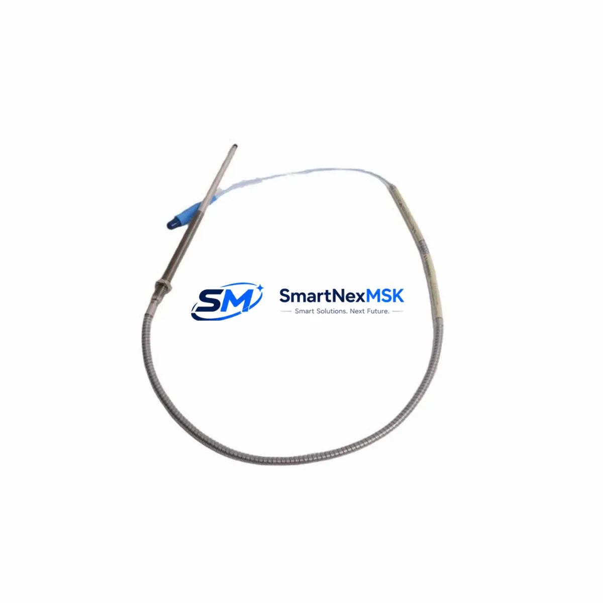
The Bently Nevada 330903-00-12-05-02-CN is an eddy-current proximity transducer engineered for seamless integration into legacy 3300 XL Series vibration monitoring systems. As aging machinery protection platforms approach end-of-life or face discontinued spare parts availability, this transducer serves as a verified retrofit-ready replacement that preserves existing wiring infrastructure, signal conditioning chains, and Bently Nevada System 1 software compatibility without requiring full panel redesign.
Industrial facilities operating rotating machinery — including steam turbines, gas compressors, centrifugal pumps, and gearboxes — rely on continuous shaft displacement monitoring to prevent catastrophic bearing failures. When the original 330903-series transducer reaches the end of its service life or becomes unavailable through OEM channels, the 330903-00-12-05-02-CN provides a direct functional substitute with identical output characteristics: a standard -18 VDC bias voltage output, 200 mV/mil (7.87 V/mm) scale factor, and a 5 mm (0.2 in) linear measurement range. These specifications ensure that existing Bently Nevada 3300 XL Proximitor® sensor assemblies, including the companion 330130-series extension cables and 330180-series Proximitor® modules, continue to operate within calibrated parameters without reconfiguration of the monitoring rack.
Before committing to a retrofit installation, engineers should verify several critical compatibility parameters. Power supply capacity at the local junction box must support the transducer’s -24 VDC nominal supply requirement, and the existing 3300 XL monitor card — such as the 3300/16 or 3300/20 — must be confirmed to accept the signal range produced by this transducer model. Terminal block wiring at the field junction box should be inspected for correct polarity and shield grounding, as improper grounding of the coaxial cable shield is a common source of noise interference in eddy-current measurement loops. The armored extension cable connecting the transducer to the Proximitor® housing must also be verified for correct length suffix, as the -12- designation in the SKU indicates a 12-inch (305 mm) integral cable, which must match the physical installation gap between the probe tip and the Proximitor® enclosure.
Upgrade Compatibility Table
| Parameter | 330903-00-12-05-02-CN Specification | Retrofit Notes |
|---|---|---|
| Replacement Target | 330903-series proximity transducers (3300 XL) | Direct drop-in; no re-ranging required |
| Supply Voltage | -24 VDC nominal (-20 to -26 VDC) | Verify existing power supply headroom |
| Output Bias | -18 VDC at mid-range gap | Confirm monitor card input range acceptance |
| Scale Factor | 200 mV/mil (7.87 V/mm) | No recalibration of monitor card needed |
| Integral Cable Length | 12 inches (305 mm) | Match to existing Proximitor® housing distance |
| Extension Cable Compatibility | 330130-series (5 m, 9 m, 15 m options) | Inspect for continuity and shield integrity |
| Proximitor® Module Compatibility | 330180-series Proximitor® sensor | Confirm firmware revision if applicable |
| Monitor Card Compatibility | 3300/16, 3300/20, 3300/46, 3300/55 | Verify slot addressing and channel assignment |
| Communication Protocol | Analog 4–20 mA / voltage output to monitor rack | No protocol migration required |
| Installation Standard | API 670 (4th/5th Edition) | Confirm probe-to-target material and surface finish |
| Warranty | 12 Months | Covered from date of shipment; includes DOA replacement |
Retrofit Planning for Existing Automation Systems
A successful retrofit of the 330903-00-12-05-02-CN into an operating plant environment requires a structured pre-outage engineering review. The first step is to pull the existing loop drawing and confirm the full signal path: from the transducer tip, through the 330130-series extension cable, into the 330180-series Proximitor® housing, and finally into the 3300 XL monitor rack. Each segment of this chain must be individually verified before the replacement transducer is installed.
At the monitor rack level, the 3300/16 or 3300/20 monitor card must be confirmed to be in a healthy state with no latched alerts or bypassed channels. If the rack also contains a 3300/46 Keyphasor® module or a 3300/55 dual-channel monitor, those modules should be checked for correct reference signal timing, as a new transducer installation can sometimes expose pre-existing signal quality issues that were masked by a degraded original probe. The rack’s System 1 software configuration should be exported and archived before any hardware change, preserving the existing alarm setpoints, full-scale ranges, and transducer identification tags.
For facilities that also operate Bently Nevada 3500-series racks in parallel with legacy 3300 XL infrastructure, the retrofit process may involve coordinating signal handoff between the two platforms. In these mixed-generation environments, the 3500/42M position monitor or 3500/40M proximitor I/O module may be receiving mirrored signals from the same shaft measurement plane, and any change to the transducer must be reflected in both rack configurations. Similarly, if the plant’s DCS — such as a Honeywell Experion PKS or an Emerson DeltaV system — is receiving 4–20 mA retransmission outputs from the 3300 XL rack, the DCS historian tags and alarm management system should be reviewed to ensure continuity of the vibration data stream during and after the transducer swap.
HMI screens displaying shaft displacement trends should be reviewed before the outage window. If the facility uses a System 1 Evolution workstation or a third-party SCADA platform, the engineering team should confirm that the transducer channel tag name, engineering unit scaling, and full-scale display range are correctly mapped to the replacement unit’s output. A mismatch in scale factor display — even if the physical measurement is correct — can trigger nuisance alarms or mask genuine machinery anomalies during the post-installation commissioning period.
Field commissioning of the 330903-00-12-05-02-CN follows a standard gap-setting procedure: with the machine at rest, the probe tip is positioned at the nominal gap distance (typically 1.0 to 1.5 mm for a 5 mm range transducer) and the output voltage is measured at the Proximitor® terminal strip to confirm the -18 VDC bias. A calibrated gap tool or a non-contact gap measurement device should be used to set the final installation gap before the locknut is torqued. The output linearity should then be verified across the full measurement range using a ramp test or a static gap sweep before the machine is returned to service.
Downtime Control During System Migration
Minimizing unplanned downtime during a proximity transducer replacement is a primary concern for maintenance teams operating continuous-process equipment. The 330903-00-12-05-02-CN is designed to support a hot-swap replacement strategy in facilities where the 3300 XL monitor rack supports channel bypass functionality. By placing the affected channel in bypass mode prior to transducer removal, the monitor rack continues to process signals from all other channels without generating a spurious machinery protection trip, allowing the replacement to proceed without a full machine shutdown in some configurations.
Where a controlled outage is required, the replacement procedure should be sequenced to minimize the time the shaft measurement plane is unmonitored. A pre-staged replacement kit — including the 330903-00-12-05-02-CN transducer, a verified 330130-series extension cable, and a calibrated gap tool — should be assembled and bench-tested before the outage window opens. The original program logic in the 3300 XL rack, including all alarm setpoints, danger levels, and time-delay settings, must be documented and preserved. If the rack is connected to a Bently Nevada TDI (Transient Data Interface) or a System 1 data acquisition server, the data collection session should be paused and restarted cleanly after the new transducer is commissioned to avoid corrupting the historical trend database.
Post-installation, a 30-minute steady-state monitoring period at normal operating speed is recommended before removing the channel bypass and returning the machinery protection system to its fully armed state. During this period, the vibration amplitude, DC gap voltage, and 1X/2X frequency components should be compared against the pre-outage baseline to confirm that the replacement transducer is performing within expected parameters. Any deviation greater than 10% from the historical baseline should be investigated before the machine is returned to full load.
Retrofit Support FAQ
Q: Is the 330903-00-12-05-02-CN a direct replacement for my existing 330903-series transducer?
A: Yes. The 330903-00-12-05-02-CN is a direct functional replacement for other 330903-series proximity transducers used in Bently Nevada 3300 XL vibration monitoring systems. The output scale factor (200 mV/mil), bias voltage (-18 VDC), and supply voltage (-24 VDC) are identical, so no recalibration of the monitor card or Proximitor® module is required. Confirm the integral cable length suffix (-12-) matches your installation geometry before ordering.
Q: What wiring checks should I perform before installing the replacement transducer?
A: Inspect the 330130-series extension cable for continuity on both the center conductor and the shield. Verify that the shield is grounded at one end only (typically at the Proximitor® housing) to prevent ground loops. Check the terminal block connections at the field junction box for correct polarity and confirm that the supply voltage at the Proximitor® input terminals is within the -20 to -26 VDC range. Any deviation outside this range should be corrected at the power supply before the new transducer is installed.
Q: How do I verify compatibility with my 3300 XL monitor card before installation?
A: Pull the monitor card’s configuration record from System 1 or the rack’s local configuration port and confirm that the transducer type is set to 330903-series and the scale factor is set to 200 mV/mil. If the card was previously configured for a different transducer model with a different scale factor, the configuration must be updated before the replacement transducer is installed. Contact your Bently Nevada system integrator or our technical support team if you need assistance with card reconfiguration.
Q: What does the 12-month warranty cover, and what is the process for a warranty claim?
A: The 12-month warranty covers manufacturing defects and functional failures under normal operating conditions, commencing from the date of shipment. It includes a dead-on-arrival (DOA) replacement policy: if the transducer fails to meet its published specifications upon receipt, we will ship a replacement unit at no charge. To initiate a warranty claim, contact our sales team with the order number, the failed unit’s serial number, and a description of the failure mode. Warranty does not cover damage resulting from incorrect installation, overvoltage conditions, or mechanical impact to the probe tip.
© 2026 SMARTNEXMSK. All rights reserved.
Original Source: https://smartnexmsk.com
Contact: sales@smartnexmsk.com | +86 18259474341


