Bently Nevada 330903-00-17-05-01-00 Retrofit-Ready Proximity Transducer for 3300 XL Control Systems
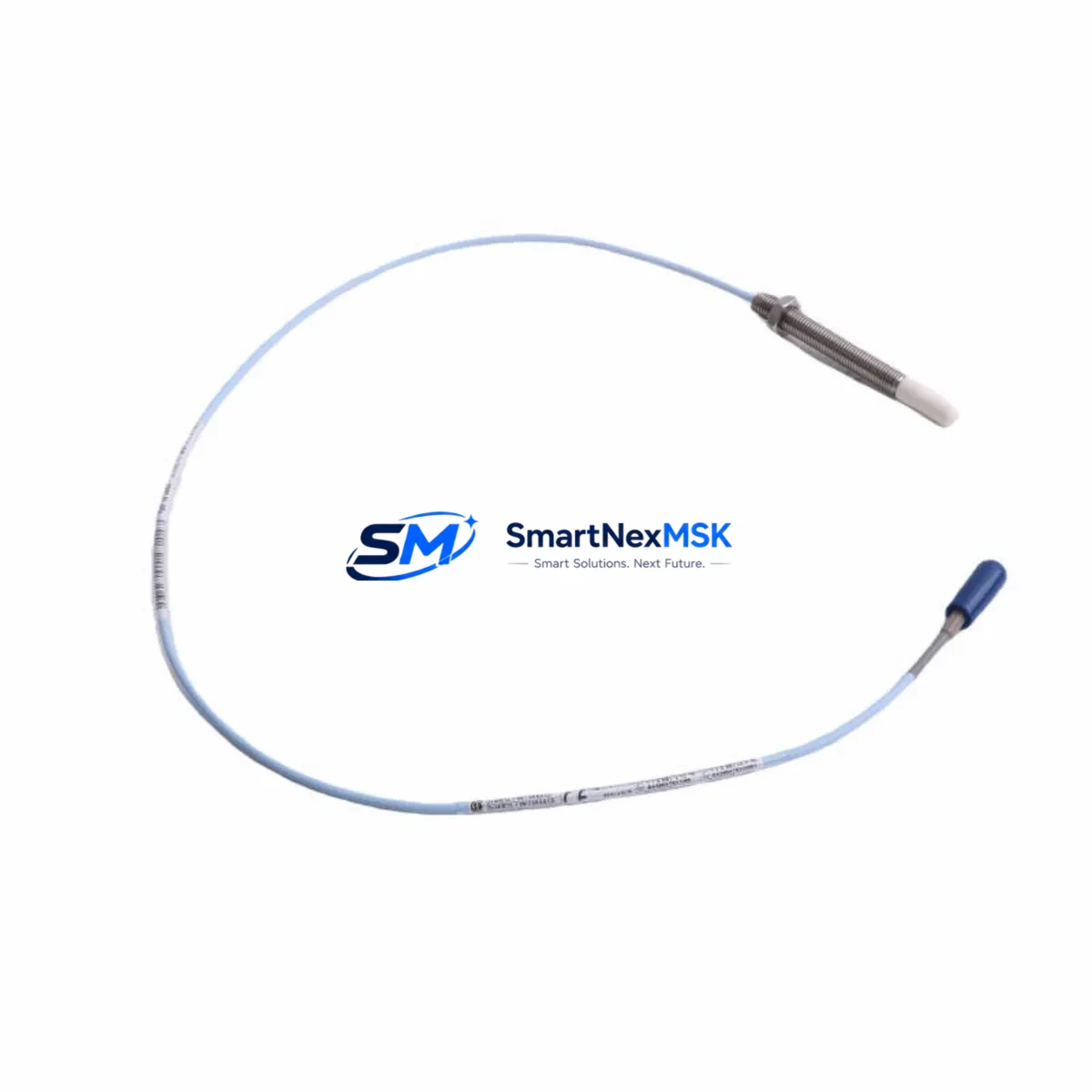
The Bently Nevada 330903-00-17-05-01-00 is an 8mm proximity transducer engineered for seamless integration into legacy and active 3300 XL Series vibration monitoring systems. As industrial facilities face increasing pressure to extend the operational life of aging machinery protection infrastructure, this transducer serves as a verified drop-in replacement for discontinued NSv (Non-contact Speed and Vibration) sensor assemblies. Whether you are managing a planned outage, responding to an unplanned sensor failure, or executing a phased control system modernization, the 330903-00-17-05-01-00 delivers the signal fidelity and mechanical compatibility required to restore full system functionality with minimal downtime.
This transducer is fully compatible with the Bently Nevada 3300 XL 8mm Proximity Transducer System, which includes the standard extension cable (330130 series) and the 3300 XL proximitor sensor (330180 series). When replacing a failed or end-of-life unit, engineers must confirm that the existing extension cable length matches the replacement transducer’s calibrated range. The 330903-00-17-05-01-00 is factory-calibrated for use with AISI 4140 steel target material; if your rotating shaft is composed of a different alloy, a field recalibration using the 3300 XL proximitor’s internal adjustment may be required before commissioning.
Upgrade Compatibility Table
| Parameter | Details |
|---|---|
| SKU / Part Number | 330903-00-17-05-01-00 |
| Series Compatibility | Bently Nevada 3300 XL NSv System |
| Sensor Type | 8mm Eddy-Current Proximity Transducer |
| Mounting Thread | M10 x 1 (standard 3300 XL bracket compatible) |
| Cable Interface | Compatible with 330130 series extension cables |
| Proximitor Compatibility | 330180 series 3300 XL Proximitor Sensor |
| Target Material (Nominal) | AISI 4140 Steel |
| Signal Output | -18 VDC nominal bias, linear range per 3300 XL spec |
| Communication / Protocol | Analog (4–20 mA / voltage), compatible with 3500 rack I/O modules |
| Replacement Recommendation | Direct drop-in for discontinued NSv transducer assemblies |
| Commissioning Note | Verify gap voltage at installation; adjust proximitor if target alloy differs |
| Warranty | 12 Months from date of shipment |
Retrofit Planning for Existing Automation Systems
Successful integration of the 330903-00-17-05-01-00 into an existing machinery protection architecture requires a structured pre-installation review. Begin by auditing the current rack configuration. In most 3300 XL installations, the transducer feeds signal into a 3300 XL 16-mm Dual Vibration Monitor or a dedicated thrust position monitor card seated in the 3500 monitoring rack. Confirm that the monitor card firmware version supports the signal range of the replacement transducer, particularly if the original unit was an early-generation NSv assembly.
Terminal wiring is a critical checkpoint. The 330903-00-17-05-01-00 uses the standard Bently Nevada three-wire configuration: power, common, and signal output. Cross-reference the existing field wiring against the 3300 XL system wiring diagram before disconnecting the failed unit. Mislabeled field cables are a common source of commissioning delays in retrofit projects, especially in facilities where the original installation documentation has not been maintained.
If the retrofit is part of a broader migration from a 3300 XL platform to the newer Bently Nevada 3500 Series, additional planning is required. The 3500/42M Proximitor I/O Module accepts the same transducer signal but requires a different rack backplane slot assignment and a corresponding update to the System 1 Evolution software configuration. During this transition, engineers frequently need to source the 3500/15 Power Supply Module, the 3500/22M Transient Data Interface, and updated I/O terminal blocks to complete the rack build-out. Procurement of these components in parallel with the transducer order reduces total project lead time.
For facilities running Bently Nevada System 1 software for condition monitoring, replacing the transducer also triggers a channel re-verification workflow. The software’s database must be updated to reflect the new transducer serial number, calibration coefficients, and gap voltage baseline. This step is often overlooked during emergency replacements and can result in false alarm conditions or suppressed alerts if left uncorrected. Coordinate with your System 1 administrator to complete the channel update before returning the machine to service.
In applications where the 330903-00-17-05-01-00 is used for radial vibration measurement on steam turbines or compressors, the retrofit plan should also address HMI screen updates. Operators relying on a GE iFIX, Wonderware InTouch, or Ignition SCADA display will need the corresponding tag database updated to reflect any channel address changes introduced during the rack reconfiguration. Coordinate HMI updates with the control room team before the planned outage window to avoid operator confusion during startup.
Downtime Control During System Migration
Minimizing unplanned downtime is the primary operational concern when replacing proximity transducers in live machinery protection systems. The recommended approach is a hot-swap procedure performed during a scheduled maintenance window, with the machine brought to a safe stop and the 3500 or 3300 XL rack placed in bypass mode for the affected channel only. Bypassing a single channel rather than the entire rack preserves protection coverage on all other measurement points throughout the replacement procedure.
Before removing the failed 330903-series transducer, document the existing gap voltage reading from the proximitor front panel or System 1 display. This baseline value is essential for verifying correct installation of the replacement unit. After mounting the new transducer and reconnecting the extension cable, adjust the probe gap to achieve a bias voltage within the linear range specified in the 3300 XL calibration data sheet — typically between -10 VDC and -18 VDC depending on the target material and gap distance.
Once the gap is set, remove the channel bypass and observe the vibration reading for a minimum of 15 minutes at operating speed before confirming the replacement is complete. Compare the live reading against historical baseline data stored in System 1 to validate that the new transducer is performing within expected parameters. If the reading deviates by more than 10% from the historical baseline at the same operating condition, re-inspect the mounting bracket alignment and target surface condition before releasing the machine to production.
For facilities without an immediate spare on hand, SMARTNEXMSK maintains in-stock inventory of the 330903-00-17-05-01-00 and can support same-day dispatch for urgent requirements. All units are function-tested prior to shipment and include a calibration verification report.
Retrofit Support FAQ
Q1: Is the 330903-00-17-05-01-00 a direct replacement for all NSv transducer variants in the 3300 XL system?
A: The 330903-00-17-05-01-00 is a direct mechanical and electrical replacement for the standard 8mm NSv transducer assemblies used in the 3300 XL system. However, if your installation uses a non-standard cable length or a special-order bracket configuration, verify dimensional compatibility before ordering. Contact our technical team with your existing part number for a confirmed cross-reference.
Q2: What commissioning steps are required after installation?
A: After mounting and wiring, set the probe gap to achieve the correct bias voltage per the 3300 XL calibration specification. Update the System 1 channel database with the new transducer serial number and calibration coefficients. Remove the channel bypass, observe live readings at operating speed, and compare against historical baseline data before releasing the machine.
Q3: Can this transducer be used with the Bently Nevada 3500 Series rack?
A: Yes, with the appropriate 3500/42M Proximitor I/O Module, the 330903-00-17-05-01-00 signal is compatible with the 3500 rack architecture. A rack configuration update in System 1 and terminal block re-wiring to the 3500 I/O format will be required. Consult the 3500 system wiring diagram for channel address assignments.
Q4: What does the 12-month warranty cover?
A: All units supplied by SMARTNEXMSK carry a 12-month warranty from the date of shipment, covering manufacturing defects and functional failures under normal operating conditions. Each unit is function-tested and ships with a calibration verification report. Warranty claims are processed within 5 business days of receipt of the returned unit.
© 2026 SMARTNEXMSK. All rights reserved.
Original Source: https://smartnexmsk.com
Contact: sales@smartnexmsk.com | +86 18259474341


