Bently Nevada 330903-00-17-05-02-00 Retrofit-Ready Proximity Probe for 3300 NSv Control Systems
When aging vibration monitoring infrastructure demands a reliable upgrade path, the Bently Nevada 330903-00-17-05-02-00 proximity probe delivers a proven, retrofit-ready solution for facilities operating legacy 3300 NSv eddy-current measurement systems. Designed as a direct mechanical and electrical replacement for discontinued or worn probe assemblies, this unit enables maintenance engineers to restore full vibration monitoring capability with minimal downtime and without requiring changes to existing wiring, conduit routing, or signal conditioning hardware.
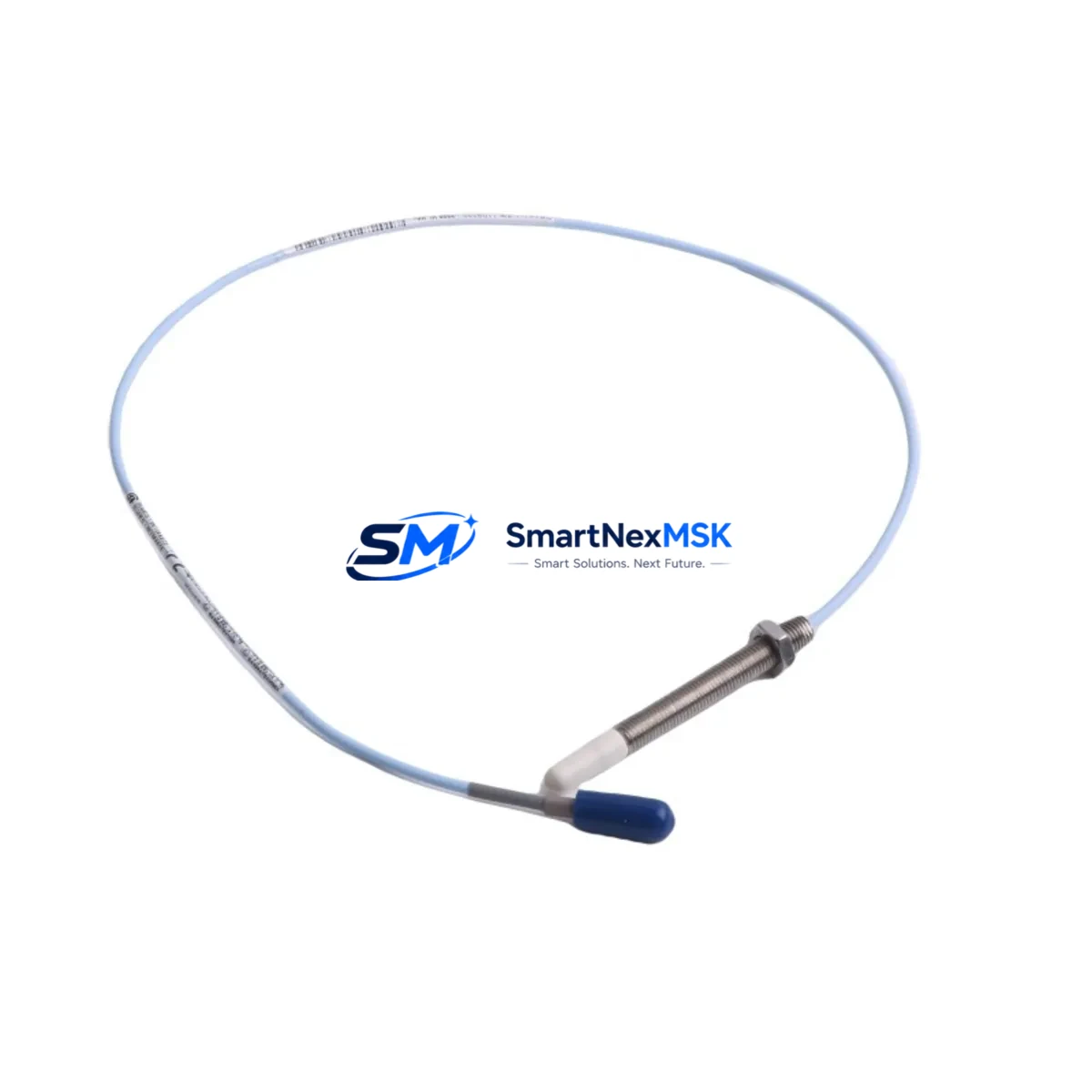
The 330903-00-17-05-02-00 is a 5-metre extension cable proximity probe from the Bently Nevada 3300 NSv series, engineered to interface directly with the 3300/16 proximitor sensor and compatible signal conditioning modules. Its eddy-current operating principle provides non-contact, continuous shaft displacement measurement — a critical function in rotating machinery protection for turbines, compressors, pumps, and gearboxes across heavy industrial sectors. The probe’s 17mm tip diameter and standardised connector format ensure it seats correctly in existing probe holders and conduit fittings without mechanical modification.
Upgrade Compatibility Table
| Parameter | Specification / Retrofit Guidance |
|---|---|
| SKU / Part Number | 330903-00-17-05-02-00 |
| Series | Bently Nevada 3300 NSv |
| Probe Type | Eddy-Current Proximity Probe |
| Cable Length | 5 metres (extension cable) |
| Tip Diameter | 17 mm |
| Operating Gap Range | 0.25 mm – 2.54 mm (nominal) |
| Supply Voltage | -24 VDC (via proximitor) |
| Output Signal | -2 VDC to -18 VDC (linear range) |
| Temperature Range | -35°C to +177°C (probe body) |
| Interface Compatibility | 3300/16 Proximitor, 3500/42 Proximitor, 3300 XL series |
| Connector Type | Standard BNC / coaxial, compatible with existing 3300 NSv wiring |
| Replacement Scope | Direct drop-in for 330903-00-17-05-02-00 and compatible 3300 NSv probe variants |
| Installation Requirement | No mechanical modification required; verify probe holder thread and gap setting |
| Communication Compatibility | Analogue signal; compatible with 3500 rack-based monitoring systems via existing cabling |
| Commissioning Check | Gap voltage verification, scale factor confirmation, OK/NOT OK relay output test |
| Warranty | 12-Month Warranty — covers manufacturing defects and functional performance |
Retrofit Planning for Existing Automation Systems
A successful retrofit begins well before the probe is physically replaced. Engineers planning a 330903-00-17-05-02-00 swap-out should first audit the existing 3300/16 proximitor sensor to confirm it is operating within its specified supply current and output impedance range. If the proximitor itself shows signs of drift or calibration loss, replacing it alongside the probe — rather than sequentially — eliminates a second planned outage. In many installations, the proximitor is mounted inside a junction box or marshalling cabinet adjacent to the machine, and its terminal block connections can be documented and replicated exactly during the probe changeover.
Cable routing is another critical consideration. The 330903-00-17-05-02-00 uses a 5-metre extension cable, which in most installations connects the probe body to the proximitor via a coaxial armoured conduit. Before pulling the new probe cable, verify that the existing conduit inner diameter accommodates the replacement cable’s outer jacket without excessive bending radius. In facilities where the original cable has been in service for more than a decade, it is common practice to replace the 330130-080-00-00 armoured extension cable at the same time to eliminate a latent failure point.
For sites running a Bently Nevada 3500 rack monitoring system, the retrofit process also involves confirming that the 3500/42M proximitor monitor card is configured for the correct probe scale factor and gap voltage. The 3500 rack’s configuration software allows engineers to verify channel assignments, alert setpoints, and danger thresholds without taking the entire rack offline — a significant advantage when only one channel requires a probe replacement. If the facility uses a System 1 Evolution condition monitoring platform, the channel configuration can be exported before the outage and re-imported after commissioning to preserve all historical baseline data and alarm logic.
Where the existing installation includes a 3300/55 dual-channel monitor or a 3300/65 thrust position monitor, engineers should cross-reference the probe’s scale factor against the monitor’s configured input range. Mismatched scale factors are a common source of false alarms following probe replacements and can be resolved through the monitor’s front-panel configuration menu or via the Rack Configuration Software (RCS). Documenting the pre-replacement scale factor and gap voltage reading — typically recorded in the machine’s vibration baseline log — provides the reference point for post-installation verification.
In facilities where the control system interfaces with a DCS platform such as a Honeywell Experion PKS or an Emerson DeltaV, the 4–20 mA or hardwired relay outputs from the 3500 rack should be verified at the DCS I/O termination panel after the probe is commissioned. This step confirms that the signal chain from probe tip to control room display is intact and that no wiring disturbance during the retrofit has introduced an open circuit or ground fault. For sites using a Modbus RTU or FOUNDATION Fieldbus communication link between the 3500 rack and the DCS, a communication health check — confirming register mapping and polling cycle integrity — should be included in the commissioning checklist.
Finally, if the machine being monitored is part of a safety instrumented system (SIS), the probe replacement must be coordinated with the site’s functional safety engineer to ensure that the SIS logic solver — often a Triconex Tricon or HIMA HIMatrix safety controller — receives a valid, in-range signal throughout the commissioning window. A bypass management procedure, documented in the site’s management of change (MOC) system, should be in place before any probe is physically disconnected.
Downtime Control During System Migration
Minimising unplanned downtime during a proximity probe retrofit requires a structured approach that preserves the original control logic and alarm architecture while the physical replacement is carried out. The most effective strategy is to treat the probe swap as a hot-standby changeover: the replacement 330903-00-17-05-02-00 is pre-gapped and verified on a bench fixture before the machine is taken offline, so that the installation window is limited to the physical pull-and-replace operation and the final gap voltage confirmation at the proximitor terminal.
For continuous-process facilities — refineries, power stations, and chemical plants — where even a brief monitoring gap carries operational risk, the preferred approach is to use the 3500 rack’s channel bypass function to place the affected channel in a known-safe state while the probe is changed. The bypass status is logged by the System 1 platform and can be time-stamped against the work order for audit purposes. Once the new probe is installed and the gap voltage is confirmed within the linear range (typically -10 VDC ±0.5 VDC at the nominal operating gap), the bypass is released and the channel is returned to active monitoring.
HMI screens connected to the vibration monitoring system — whether running on a Wonderware InTouch, Ignition SCADA, or a proprietary operator interface — should be reviewed after commissioning to confirm that the channel tag is displaying a live, plausible value and that no latched alarms remain from the bypass period. A brief trend review covering the first 30 minutes of post-commissioning operation provides confidence that the new probe is tracking shaft displacement consistently with adjacent channels and with the machine’s historical vibration signature.
All replacement units supplied by SMARTNEXMSK undergo pre-shipment functional testing, including gap voltage linearity verification and insulation resistance measurement, ensuring that the probe arrives ready for installation without requiring incoming inspection. Stock availability is maintained to support both planned maintenance schedules and emergency replacement scenarios, with fast global shipping to minimise the logistics window between order placement and site delivery.
Retrofit Support FAQ
Q1: Is the 330903-00-17-05-02-00 a direct drop-in replacement for other 3300 NSv probe variants?
The 330903-00-17-05-02-00 is directly interchangeable with other 330903 series probes sharing the same tip diameter (17 mm) and cable length (5 m). Variants with different cable lengths (e.g., 330903-00-17-05-01-00 at 1 m or 330903-00-17-05-03-00 at 9 m) are not direct drop-ins due to the cable length difference, which affects the system’s scale factor and requires recalibration of the proximitor. Always confirm the full part number before ordering.
Q2: What commissioning steps are required after installation?
After physical installation, verify the probe-to-target gap using a digital voltmeter at the proximitor output terminals. The gap voltage should fall within the linear range specified for the 3300/16 proximitor (typically -10 VDC at the nominal gap). Confirm the OK/NOT OK relay output is in the OK state, check the scale factor setting in the 3500 rack configuration, and review the System 1 trend for the first operational cycle to confirm stable readings.
Q3: Does the unit come with a warranty, and what does it cover?
Yes. All units supplied by SMARTNEXMSK carry a 12-month warranty covering manufacturing defects and functional performance under normal operating conditions. Each unit is functionally tested prior to shipment. Warranty claims are supported with replacement or refund, subject to inspection of the returned unit.
Q4: Can you support long-term supply for planned maintenance programmes?
Yes. SMARTNEXMSK maintains stock of the 330903-00-17-05-02-00 and related 3300 NSv series components to support both scheduled maintenance intervals and emergency replacement requirements. Blanket order arrangements and reserved stock agreements are available for facilities with recurring demand. Contact our team to discuss supply continuity planning for your site.
© 2026 SMARTNEXMSK. All rights reserved.
Original Source: https://smartnexmsk.com
Contact: sales@smartnexmsk.com | +86 18259474341


