Bently Nevada 330903-00-18-05-01-00 Retrofit-Ready Proximity Transducer for 3300 XL NSv Control Systems
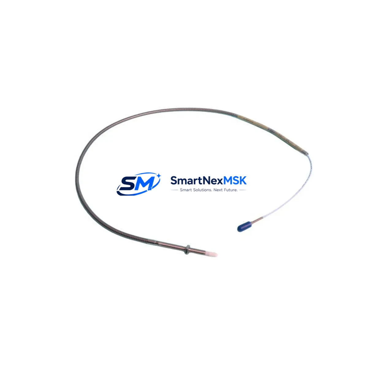
The Bently Nevada 330903-00-18-05-01-00 is an 18-inch (457 mm) proximity transducer engineered for the 3300 XL NSv (Non-contact Shaft Vibration) monitoring platform. As legacy machinery protection systems age and OEM support windows close, this transducer serves as a verified drop-in replacement for facilities undertaking vibration monitoring upgrades, control cabinet retrofits, and predictive maintenance modernization programs. Whether you are replacing a failed unit on a critical rotating machine or executing a planned migration from an older 3300 series architecture, the 330903-00-18-05-01-00 delivers the dimensional, electrical, and signal-chain compatibility required for a smooth, low-risk transition.
Designed to work within the Bently Nevada 3300 XL NSv eddy-current measurement chain, this transducer pairs directly with the 330180 extension cable and the 330130 proximitor/oscillator to form a complete proximity measurement loop. The system outputs a standard –24 VDC bias voltage signal, making it electrically compatible with existing 3300 XL monitor cards such as the 3300/16 and 3300/20 series installed in your machinery protection rack. When replacing a transducer in an operating plant, engineers must confirm that the gap voltage at the installed position falls within the linear range of –10 VDC to –18 VDC, and that the proximitor sensitivity is set to 200 mV/mil (7.87 V/mm) to match the original calibration baseline stored in the System 1 condition monitoring software.
For facilities migrating from the earlier Bently Nevada 7200 series transducers to the 3300 XL NSv platform, the 330903-00-18-05-01-00 represents the recommended upgrade path. The 7200 series used a different cable connector standard and a slightly different sensitivity curve; technicians should update the proximitor configuration and recalibrate the gap at the bearing housing before returning the machine to service. The 3300 XL monitor rack accepts both the legacy and new transducer families through the same terminal block wiring scheme, which significantly reduces rewiring time during a planned outage.
Upgrade Compatibility Table
| Parameter | 330903-00-18-05-01-00 (This Unit) | Legacy / Replaced Model |
|---|---|---|
| Platform | Bently Nevada 3300 XL NSv | Bently Nevada 3300 / 7200 Series |
| Cable Length | 18 in (457 mm) integral cable | Varies (5 in / 9 in / 18 in options) |
| Connector Type | Standard 3300 XL NSv connector | 7200 series connector (adapter may be required) |
| Output Sensitivity | 200 mV/mil (7.87 V/mm) | 200 mV/mil (verify proximitor setting) |
| Bias Voltage | –24 VDC nominal | –24 VDC nominal |
| Linear Range | –10 VDC to –18 VDC | –10 VDC to –18 VDC (confirm at installation) |
| Compatible Proximitor | 330130 Proximitor/Oscillator | 330130 / 7200-series (check part number) |
| Compatible Extension Cable | 330180 Extension Cable | 330180 / 7200-series extension cable |
| Monitor Card Compatibility | 3300/16, 3300/20 monitor cards | 3300/16, 3300/20 (same terminal block) |
| Installation Requirement | Gap calibration at bearing housing | Gap recalibration required after swap |
| Communication Protocol | Analog (4–20 mA / voltage output via monitor) | Analog (same) |
| Retrofit Recommendation | Direct drop-in for 3300 XL NSv chain | Recalibrate gap; update System 1 configuration |
| Commissioning Focus | Gap voltage, sensitivity, alarm setpoints | Verify all setpoints after replacement |
| Warranty | 12-Month Warranty — All units tested prior to shipment | |
Retrofit Planning for Existing Automation Systems
A successful retrofit of the 330903-00-18-05-01-00 into an existing machinery protection system begins well before the maintenance window opens. The first step is a full audit of the measurement chain: confirm the installed proximitor model (typically the 330130), verify the extension cable part number (330180 in most 3300 XL installations), and document the current gap voltage reading at the bearing housing. This baseline data is essential for post-installation verification and for updating the System 1 condition monitoring database.
In control cabinets housing a 3300 XL rack, the transducer signal enters the rack through a dedicated terminal block on the 3300/16 or 3300/20 monitor card. The wiring scheme uses a three-conductor shielded cable: power (–24 VDC), signal (output voltage), and common (shield/ground). Before disconnecting the old transducer, photograph the terminal block connections and record the shield grounding point — improper shield grounding is one of the most common sources of noise after a transducer replacement. The 3300 XL rack power supply module must be confirmed to have sufficient capacity to support the replacement transducer and any additional I/O modules added during the same outage.
Facilities that are simultaneously upgrading their communication infrastructure — for example, migrating from a legacy Modbus RTU link to a Profibus DP or Ethernet/IP backbone — should note that the 3300 XL monitor cards communicate upstream through the rack backplane to a gateway module. The transducer itself is an analog device; the protocol migration occurs at the monitor card or gateway level, not at the transducer. This means the 330903-00-18-05-01-00 can be installed without any changes to the communication layer, simplifying the retrofit scope.
For plants expanding their I/O footprint during the same outage, the 3300 XL rack accepts additional monitor cards in open slots, allowing engineers to add channels for axial position, differential expansion, or speed measurement without replacing the existing transducer infrastructure. Components such as the 3300/55 Keyphasor module, the 3300/46M temperature monitor, and the 3300/25 relay output module are all rack-compatible and can be installed alongside the replacement transducer during a single planned shutdown. HMI screens connected to the System 1 platform will require a tag update to reflect any new channel assignments, but existing vibration trend displays and alarm pages for the replaced transducer channel will remain intact after the gap recalibration is complete.
Downtime Control During System Migration
Minimizing unplanned downtime during a transducer replacement requires a structured pre-outage preparation protocol. Before the machine is taken offline, download and archive the current System 1 configuration file, including all alarm setpoints, danger limits, and trend buffer settings for the affected channel. This archive serves as both a rollback reference and a commissioning checklist for the replacement unit.
During the replacement window, the 330903-00-18-05-01-00 can be installed and gap-set while the machine is stationary. The target gap voltage for most steel shaft applications is –12 VDC ± 1 VDC, achievable by adjusting the transducer axial position in the probe holder until the proximitor output reads within the linear range. Once the gap is set and the locknut is torqued to specification, the monitor card channel should be placed in bypass mode before the machine is restarted to prevent spurious alarms during run-up. After the shaft reaches operating speed and the vibration signal stabilizes, the bypass is removed and the channel is returned to normal monitoring mode.
To protect original program logic in PLC-based interlock systems that receive a trip signal from the 3300 XL rack relay outputs, confirm that the relay output module (such as the 3300/25) is configured to hold its last state during the bypass period. This prevents a nuisance trip of the associated safety interlock or emergency shutdown system while the new transducer is being commissioned. Field technicians should have a laptop with the System 1 software and the rack configuration file loaded and ready at the cabinet before the outage begins, so that any setpoint adjustments can be made immediately without waiting for remote engineering support.
Retrofit Support FAQ
Q1: Is the 330903-00-18-05-01-00 a direct replacement for the older 330903-00-18-05-00-00?
A: Yes. The -01-00 revision is the current production version and is a direct functional replacement for the earlier -00-00 revision. The connector, cable length, sensitivity, and linear range are identical. No wiring changes or proximitor reconfiguration are required when swapping between these two revisions.
Q2: What commissioning steps are required after installation?
A: After mechanical installation, set the transducer gap to achieve a bias voltage of –12 VDC ± 1 VDC at the proximitor output. Verify the sensitivity reads 200 mV/mil using a calibrated gap-setting tool or a precision feeler gauge. Update the System 1 channel configuration if the transducer serial number is tracked, and confirm all alarm and danger setpoints match the archived baseline before returning the channel to service.
Q3: Can this transducer be used with a 7200-series proximitor?
A: The 330903-00-18-05-01-00 is designed for the 3300 XL NSv measurement chain and is optimized for use with the 330130 proximitor. While the eddy-current operating principle is the same, the 7200-series proximitor has a different connector and may have a different sensitivity calibration. Using a 7200-series proximitor with this transducer is not recommended without a full calibration verification. For best results, replace the proximitor with the 330130 at the same time as the transducer.
Q4: What does the 12-month warranty cover, and how are units tested before shipment?
A: All units supplied by SMARTNEXMSK are tested for electrical continuity, output sensitivity, and linear range performance prior to shipment. The 12-month warranty covers defects in materials and workmanship under normal operating conditions. Each unit ships with a test report confirming the gap voltage and sensitivity readings measured during pre-shipment inspection. Warranty claims are processed through our sales team at sales@smartnexmsk.com.
© 2026 SMARTNEXMSK. All rights reserved.
Original Source: https://smartnexmsk.com
Contact: sales@smartnexmsk.com | +86 18259474341


