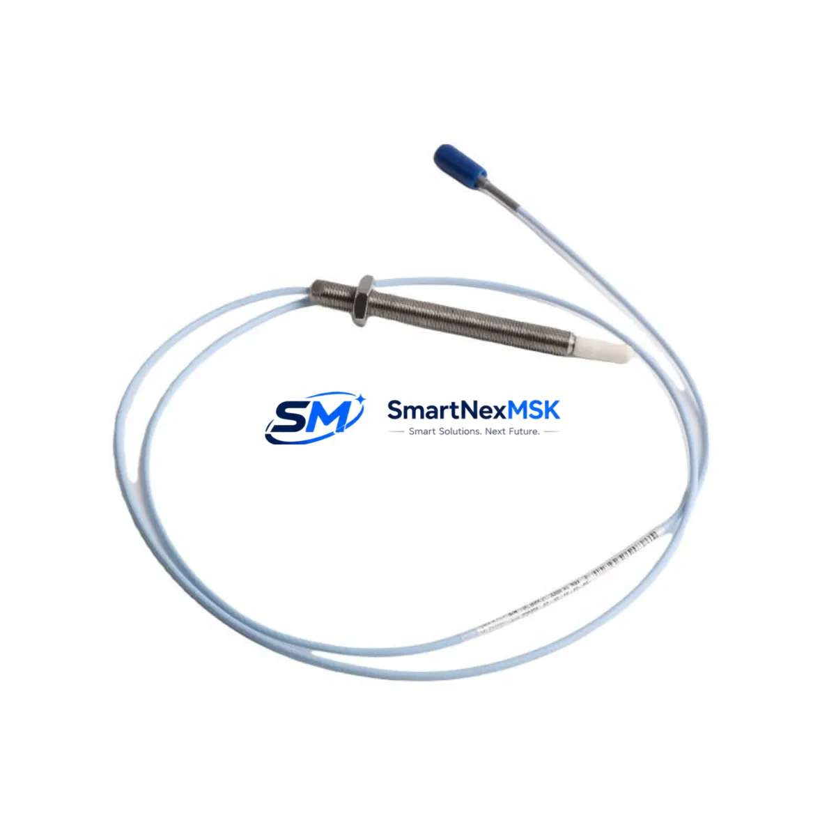
Bently Nevada 330903-00-23-05-01-00 Spare 3300 XL Automation
The Bently Nevada 330903-00-23-05-01-00 is an original eddy current proximity transducer engineered for the 3300 XL Series continuous machinery monitoring system. In rotating machinery protection applications — turbines, compressors, pumps, and gearboxes — this transducer provides the critical vibration and position signal that feeds the 3300 XL monitor rack. When this component fails or degrades, the entire protection loop is compromised, leaving rotating assets exposed to undetected shaft displacement, radial vibration exceedance, and potential catastrophic failure. Maintaining a verified spare on the shelf is not optional in high-availability plant environments; it is a fundamental element of any credible predictive maintenance and emergency response plan.
This unit ships fully tested, serialized, and packaged to OEM standards. Each 330903-00-23-05-01-00 supplied by SMARTNEXMSK is verified for output sensitivity, gap voltage linearity, and cable integrity prior to dispatch. A 12-month warranty covers manufacturing defects and performance deviation from published specifications. Worldwide express logistics are available to minimize mean time to repair (MTTR) for critical asset outages.
Spare Maintenance Table
| Parameter | Specification |
|---|---|
| Part Number | 330903-00-23-05-01-00 |
| Brand | Bently Nevada |
| Series | 3300 XL |
| Type | Eddy Current Proximity Transducer |
| Probe Length | 23 mm (as indicated by SKU segment -23-) |
| Cable Length | 5 m (as indicated by SKU segment -05-) |
| Output Sensitivity | 7.87 V/mm (200 mV/mil), nominal |
| Gap Voltage Range | −2 VDC to −18 VDC |
| Supply Voltage | −24 VDC (via 3300 XL proximitor/driver) |
| Frequency Response | DC to 10,000 Hz |
| Operating Temperature | −35°C to +177°C (probe tip) |
| Target Material Compatibility | Steel, stainless steel, chrome-moly alloys |
| Connector | Standard 3300 XL coaxial, reverse-polarity protected |
| Installation Standard | API 670 compliant |
| Application Environment | Turbines, compressors, pumps, gearboxes, fans |
| Maintenance Recommendation | Inspect gap voltage at each planned outage; replace if sensitivity drift >5% |
| Warranty | 12 months from date of shipment |
| Origin | USA (OEM) |
| Condition | Original, new or recertified — confirmed at order |
Maintenance Planning for Continuous Operation
A proximity transducer replacement is rarely an isolated event. When a 330903-00-23-05-01-00 is pulled from service, a disciplined maintenance engineer will use the opportunity to audit the entire vibration monitoring loop and the surrounding control cabinet. The 3300 XL proximitor/driver — typically the 330180-91-00 or 330180-51-00 — should be inspected for output voltage stability and connector corrosion, as a degraded driver will cause a replacement transducer to report erroneous readings immediately after installation.
The extension cable connecting the probe to the proximitor is a frequent failure point in high-vibration environments. Cables in the 330130 series should be checked for jacket cracking, shield continuity, and connector seating. A faulty cable will mimic a failed transducer and lead to unnecessary component replacement cycles. Similarly, the 3300 XL monitor module (such as the 3300/16 dual-channel vibration monitor) should be verified for alarm setpoint integrity and OK relay output status after any transducer swap.
Power supply quality directly affects transducer accuracy. The −24 VDC rail feeding the proximitor should be checked at the terminal block using a calibrated multimeter; ripple exceeding 50 mV peak-to-peak can introduce noise into the vibration signal. If the cabinet houses a Bently Nevada 3500 series rack alongside legacy 3300 XL modules, verify that the common power supply — often a 3500/15 power supply module — is within its rated load capacity after adding any replacement components.
For plants running mixed-generation machinery protection, it is common to find 330500-series junction boxes and 330850-series field wiring assemblies in the same cabinet. These passive components should be inspected for terminal oxidation and torque compliance during any transducer replacement outage. Signal isolators — particularly where the 3300 XL output feeds a DCS analog input card — should be tested for zero and span accuracy; a drifted isolator will corrupt the vibration trend data even after a perfect transducer installation.
Finally, if the plant uses a Bently Nevada System 1 software platform for online machinery diagnostics, confirm that the new transducer’s channel configuration (gap, sensitivity, and OK limits) is updated in the software database before returning the machine to service. Failure to update the digital twin will generate false OK-relay trips and may mask genuine fault conditions during the post-maintenance run-up period.
Site Replacement Workflow
Step 1 — Isolation and Lockout: Follow site LOTO procedures. De-energize the 3300 XL rack power supply and confirm zero voltage at the proximitor terminal before disconnecting the transducer cable.
Step 2 — Gap Measurement: Before removing the old transducer, record the installed gap using a feeler gauge or the existing gap voltage reading. The target gap for the 330903-00-23-05-01-00 is typically 1.0–1.5 mm (40–60 mil), yielding approximately −10 VDC at the proximitor output. Document this value for post-installation verification.
Step 3 — Transducer Removal: Unscrew the probe from the bracket using the correct spanner. Avoid bending the extension cable. Inspect the probe tip for impact damage or target material transfer, which indicates abnormal shaft contact and requires a shaft inspection before restart.
Step 4 — New Unit Installation: Thread the 330903-00-23-05-01-00 replacement into the bracket. Set the gap to the documented value. Torque to the bracket manufacturer’s specification — typically 1.5–2.0 N·m for standard 8 mm probe bodies. Reconnect the extension cable and verify connector seating.
Step 5 — Energize and Verify: Restore power to the 3300 XL rack. Measure the proximitor output voltage. Confirm the OK relay is energized and the gap voltage is within the −10 VDC ±1 VDC target. Check the System 1 or DCS trend display for a clean, noise-free signal before releasing the machine for restart.
Step 6 — Documentation: Record the replacement in the CMMS with the new unit’s serial number, installation date, and post-installation gap voltage. Schedule the next inspection interval per the plant’s predictive maintenance program.
Spare Parts Support FAQ
Q1: Is the 330903-00-23-05-01-00 a direct drop-in replacement for older 330903 variants?
A: The 330903 family shares a common mechanical envelope and electrical interface across most suffix variants. However, cable length and probe length differ by SKU segment. Always verify the -23- (probe length) and -05- (cable length) segments match your installation bracket and proximitor wiring before ordering. SMARTNEXMSK can cross-reference your existing part number and confirm compatibility prior to shipment.
Q2: What is the recommended spare inventory strategy for a plant with multiple 3300 XL loops?
A: Industry best practice for API 670-compliant machinery protection systems is to maintain a minimum of one spare transducer per monitored machine train, plus one additional unit per five installed probes as a buffer. For critical assets such as main steam turbines or high-pressure compressors, a dedicated hot-spare kit — including the transducer, extension cable, and proximitor — is strongly recommended to achieve sub-four-hour MTTR targets.
Q3: How is each unit tested before shipment?
A: Every 330903-00-23-05-01-00 dispatched by SMARTNEXMSK undergoes bench verification of output sensitivity (mV/mil), gap voltage linearity across the full measurement range, cable continuity and shield integrity, and connector mechanical retention. A test report is available upon request. Units that do not meet OEM published specifications are quarantined and not shipped.
Q4: What does the 12-month warranty cover, and how is a claim processed?
A: The 12-month warranty covers manufacturing defects, sensitivity drift beyond ±5% of nominal, and cable or connector failure under normal operating conditions. Physical damage caused by installation error, shaft contact, or chemical exposure is excluded. To initiate a warranty claim, contact sales@smartnexmsk.com with the order number, unit serial number, and a description of the observed fault. SMARTNEXMSK will arrange return logistics and ship a replacement unit within five business days of receiving the defective item.
© 2026 SMARTNEXMSK. All rights reserved.
Original Source: https://smartnexmsk.com
Contact: sales@smartnexmsk.com | +86 18259474341


