Bently Nevada 330903-00-23-05-02-00 Spare 3300 NSv: Proximity Probe Replacement for Industrial Downtime Control
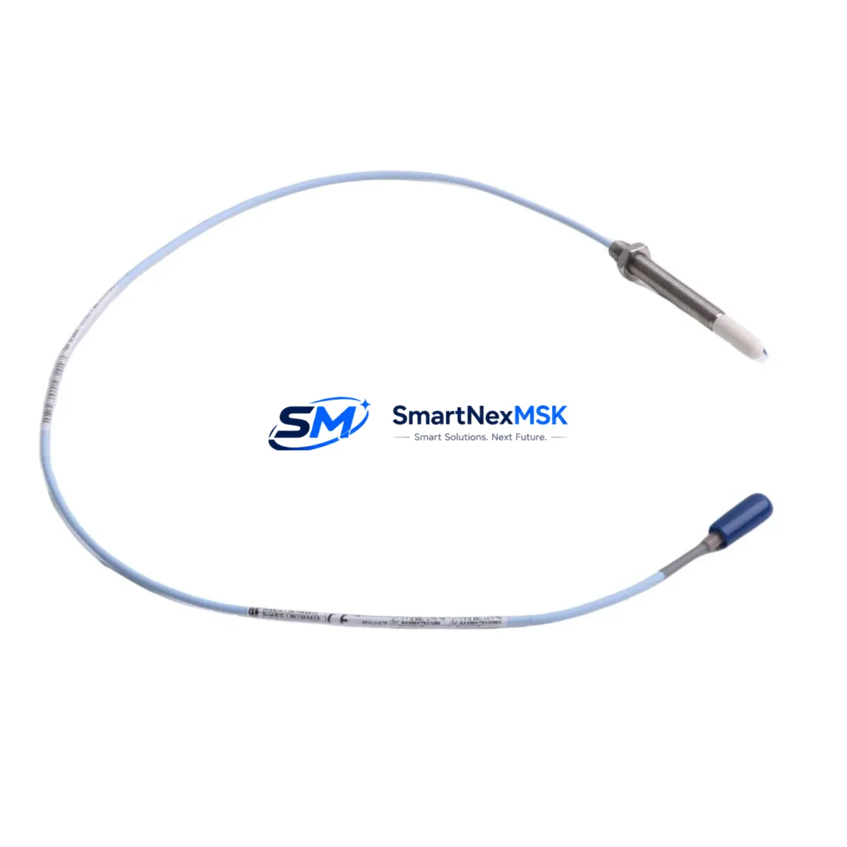
The Bently Nevada 330903-00-23-05-02-00 is an 8mm eddy current proximity probe designed for the 3300 NSv series vibration monitoring system. As a critical sensing element in rotating machinery protection, this probe measures shaft displacement and radial vibration in real time, feeding data to the 3300 NSv rack-mounted monitors that trigger alarms and shutdowns when thresholds are exceeded. Holding a verified spare on the shelf is the single most effective way to eliminate unplanned downtime caused by probe failure in turbines, compressors, pumps, and gearboxes.
Each unit shipped by SMARTNEXMSK is sourced from authorized supply channels, electrically tested against Bently Nevada factory specifications, and packaged for long-term storage. The probe is a direct drop-in replacement for the original 330903-00-23-05-02-00 without requiring recalibration of the 3300 NSv monitor, provided the extension cable and proximitor remain within the qualified system gap voltage range. A 12-month warranty covers every unit against manufacturing defects and electrical failure under normal operating conditions.
Spare Maintenance Table
| Parameter | Specification |
|---|---|
| Part Number | 330903-00-23-05-02-00 |
| Brand | Bently Nevada |
| Series | 3300 NSv |
| Probe Type | Eddy Current Proximity Probe |
| Probe Diameter | 8 mm |
| Cable Length | 5 m (integral cable) |
| Connector | MIL-C-5015 style, compatible with 3300 NSv extension cables |
| Operating Temperature | -35 °C to +177 °C (probe tip) |
| Supply Voltage | -24 VDC (via proximitor/driver) |
| Output Range | -2 VDC to -18 VDC (linear range) |
| Sensitivity | 7.87 V/mm (200 mV/mil) |
| Target Material Compatibility | AISI 4140 steel, AISI 4340 steel (standard) |
| Installation | Threaded body, jam-nut mounting, gap set to -10 VDC nominal |
| Application Environment | Steam turbines, gas turbines, centrifugal compressors, pumps, gearboxes |
| Compatibility | 3300 NSv Monitor, 3300 XL Monitor (with correct proximitor), 3500 series (verify proximitor) |
| Maintenance Recommendation | Replace probe and extension cable as a matched set; re-verify gap voltage after installation |
| Warranty | 12 Months — covers electrical failure and manufacturing defects |
| Pre-shipment Test | Output linearity, insulation resistance, connector integrity |
Maintenance Planning for Continuous Operation
When a 330903-00-23-05-02-00 probe is flagged during a routine control cabinet inspection or vibration trend review, the replacement scope should extend beyond the probe itself. Maintenance engineers should treat the event as an opportunity to audit the entire measurement chain and adjacent components in the same monitoring loop.
Start with the 330130-080-00-00 extension cable that connects the probe to the proximitor. Extension cables accumulate micro-fractures at the conduit entry points over years of thermal cycling, and a degraded cable will produce the same erratic gap voltage symptoms as a failed probe. Replace the cable whenever the probe is changed to avoid a repeat callout within weeks.
The 330180-X1-05 proximitor/driver module (or equivalent NSv-series driver) should be bench-tested after probe replacement. A proximitor that has been operating with a shorted or open-circuit probe may have sustained internal damage. Confirm the output voltage sweeps linearly across the full gap range before returning the loop to service.
Inside the 3300 NSv rack, inspect the 3300/16-XX-XX-XX-XX-XX monitor card for alarm setpoint integrity. Vibration trips are stored in non-volatile memory, but a card that has experienced a power transient may have corrupted threshold values. Cross-reference the setpoints against the machinery protection philosophy document before re-enabling the trip relay.
The 3300/20 power supply module feeding the NSv rack deserves attention during any probe replacement outage. A power supply operating near its rated load with marginal output regulation will cause all probes in the rack to read slightly high or low simultaneously — a subtle fault that is easy to misattribute to individual probe drift. Measure the -24 VDC rail under load and compare against the module’s specification.
For machines with both radial and axial measurement, the 330905-00-23-05-02-00 thrust probe (same 8mm body, different cable configuration) should be visually inspected at the same time. Thrust probes on the same shaft share the same thermal and chemical environment as radial probes, and simultaneous degradation is common in high-temperature or wet-gas service.
Terminal blocks and 3300 NSv I/O junction boxes should be checked for corrosion, loose terminations, and moisture ingress. A single high-resistance connection in the signal return path introduces a DC offset that shifts the apparent gap voltage and can cause nuisance trips or mask real vibration increases.
Where the 3300 NSv system interfaces with a DCS or safety PLC via 4–20 mA output cards or relay output modules, verify that the analog output scaling and relay logic remain consistent with the updated probe installation. A probe repositioned even slightly during replacement will change the static gap voltage and may shift the 4–20 mA zero point.
Finally, review the Keyphasor® module (typically a 3300/25 or 3500/25) if the machine uses phase-referenced vibration analysis. The Keyphasor probe is often the same 8mm eddy current type and is subject to identical wear mechanisms. Confirming its gap voltage and signal quality during a planned outage costs minutes and prevents an unplanned return to the machine.
Site Replacement Workflow
Step 1 — Isolation and permit: Obtain a lock-out/tag-out permit for the machine. De-energize the 3300 NSv rack or place the affected channel in bypass mode to prevent a spurious trip during probe removal.
Step 2 — Document the existing installation: Record the current gap voltage (typically displayed on the monitor front panel or via System 1 software) and the physical probe-to-shaft gap measurement. This baseline is essential for verifying the replacement installation.
Step 3 — Remove the old probe: Back off the jam nut, unscrew the probe body, and disconnect the extension cable at the junction box. Inspect the probe tip for impact marks, chemical attack, or heat discoloration that may indicate a root cause beyond normal wear.
Step 4 — Install the 330903-00-23-05-02-00 replacement: Thread the new probe into the bracket, set the physical gap to the value specified in the machinery OEM documentation (commonly 1.0–1.5 mm for 8mm probes), and torque the jam nut to specification. Reconnect the extension cable.
Step 5 — Verify gap voltage: Re-energize the proximitor and confirm the gap voltage reads within ±0.5 VDC of the documented baseline. Adjust the physical gap if necessary. A reading outside the linear range (-2 VDC to -18 VDC) indicates a wiring error, incompatible target material, or a faulty replacement unit.
Step 6 — Functional test and return to service: Remove the channel bypass, confirm the monitor displays a healthy vibration reading consistent with machine-at-rest levels, and restore the trip relay. Update the maintenance management system with the replacement date, new probe serial number, and gap voltage as-found/as-left values.
This workflow applies equally to legacy 3300 XL installations where the 330903-00-23-05-02-00 is used as a compatible replacement, reducing the need to stock separate probe part numbers for older and newer monitor generations.
Spare Parts Support FAQ
Q: Is the 330903-00-23-05-02-00 compatible with both 3300 NSv and 3300 XL monitor systems?
A: Yes. The probe body, sensitivity, and connector are identical across both monitor generations. Compatibility depends on the proximitor/driver model installed in the rack — confirm the driver is rated for the 8mm probe family before installation. SMARTNEXMSK can provide compatibility verification based on your rack configuration.
Q: How should I store spare probes to maximize shelf life?
A: Store in the original anti-static packaging in a dry environment between 0 °C and 40 °C, away from strong magnetic fields and solvents. The integral cable should be coiled loosely with a minimum bend radius of 50 mm. Under these conditions, shelf life exceeds five years without performance degradation. Inspect the connector pins and cable jacket annually.
Q: What does the 12-month warranty cover, and how is a claim processed?
A: The warranty covers electrical failure, output non-linearity outside factory specification, and physical defects present at the time of shipment. It does not cover damage from incorrect installation, mechanical impact, or chemical exposure. To initiate a claim, contact sales@smartnexmsk.com with the order number, failure description, and gap voltage readings. SMARTNEXMSK will arrange return shipping and provide a replacement or refund within the agreed lead time.
Q: Can SMARTNEXMSK supply matched probe-and-extension-cable sets for a planned outage?
A: Yes. Matched sets consisting of the 330903-00-23-05-02-00 probe and the appropriate 330130-series extension cable can be kitted and shipped together. Ordering matched sets eliminates the risk of impedance mismatch between probe and cable and simplifies incoming inspection. Contact us with your required cable length and connector type to receive a quotation.
© 2026 SMARTNEXMSK. All rights reserved.
Original Source: https://smartnexmsk.com
Contact: sales@smartnexmsk.com | +86 18259474341


