Bently Nevada 330903-00-23-10-01-00 Retrofit-Ready Proximity Transducer for 3300 XL Control Systems
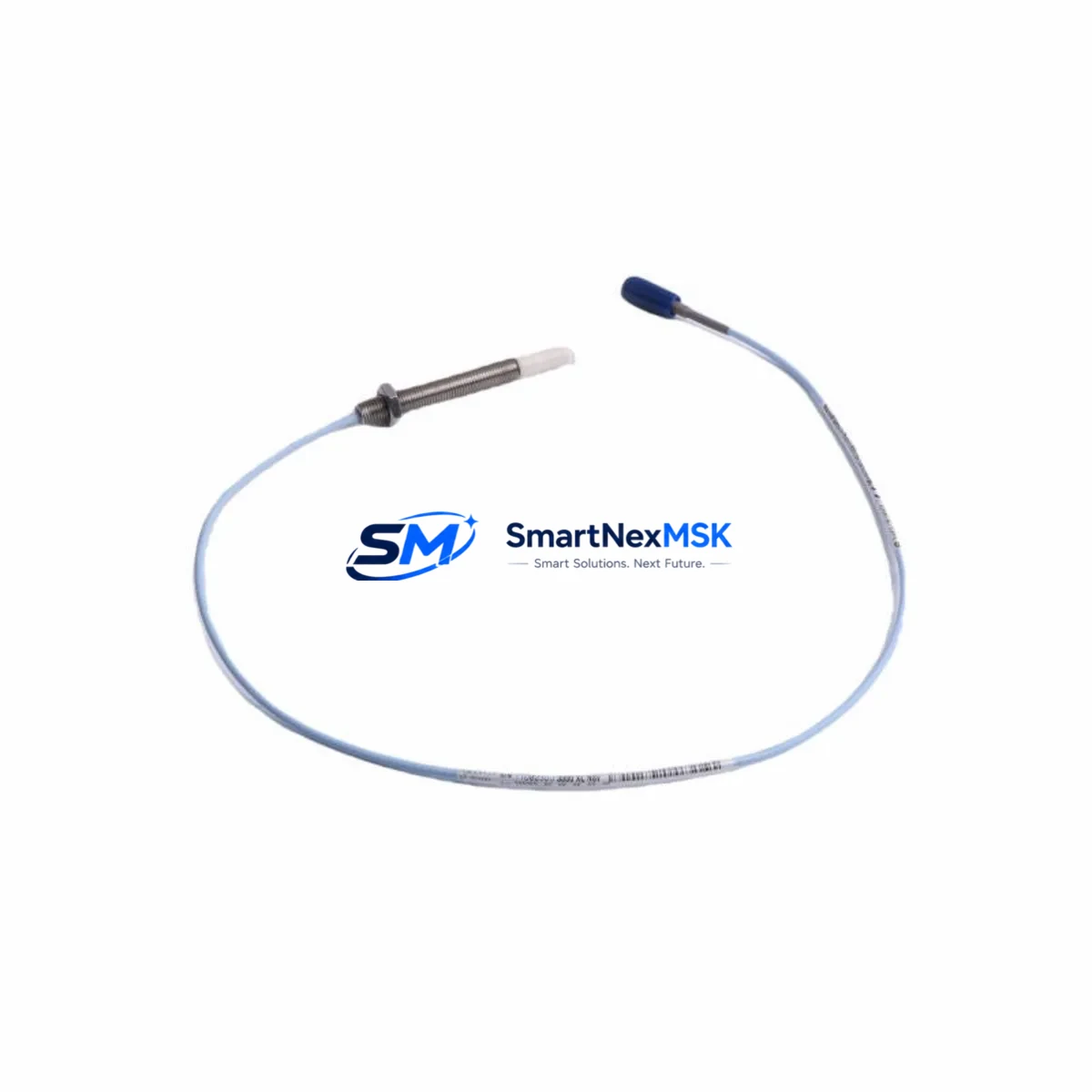
The Bently Nevada 330903-00-23-10-01-00 is a high-precision eddy-current proximity transducer engineered for the 3300 XL Series vibration monitoring platform. As legacy 3300 XL installations approach end-of-support cycles, this unit serves as the primary retrofit solution for facilities seeking to extend operational life, replace discontinued sensors, and maintain continuous machinery protection without a full system overhaul. Whether you are upgrading a turbine monitoring cabinet, replacing a failed transducer on a compressor train, or migrating from an older 3300 Series rack to the current 3300 XL architecture, the 330903-00-23-10-01-00 delivers verified drop-in compatibility with minimal downtime exposure.
This transducer operates within the standard Bently Nevada 5 mm tip clearance range and is fully compatible with the 3300 XL 8mm Extension Cable system. It integrates directly with the 3300 XL Proximitor® sensor driver, eliminating the need for signal conditioning adapters or driver recalibration in most retrofit scenarios. The 330903-00-23-10-01-00 is designed to interface with the 3500/42M Proximitor®/Seismic Monitor module and the 3500/40M Proximitor®/Seismic Monitor, both of which are widely deployed in rotating machinery protection systems across petrochemical, power generation, and heavy industrial facilities.
When planning a retrofit using the 330903-00-23-10-01-00, engineers must verify several critical parameters before installation. Power supply capacity at the rack level should be confirmed against the 3300 XL power supply module specifications — typically the 3300 XL Power Supply — to ensure the additional transducer load does not exceed available headroom. Terminal wiring must be cross-referenced against the original loop drawing; the 330903-00-23-10-01-00 uses a standard three-wire coaxial configuration compatible with existing field cable runs in most 3300 XL installations, but connector orientation and shield grounding points should be verified at the junction box before energizing the loop.
Backplane interface compatibility is a key consideration when the transducer is being installed into a mixed-generation rack. If the host rack contains both legacy 3300 Series I/O modules and current 3300 XL modules, module addressing must be re-confirmed in the System 1 Evolution software or the rack configuration utility to prevent channel mapping conflicts. Program logic compatibility should be reviewed in the Bently Nevada System 1 database — particularly alarm setpoints, gap voltage thresholds, and OK relay logic — to ensure that the replacement transducer’s sensitivity factor (typically 7.87 V/mm for this model) matches the configured value in the monitoring software.
HMI screen updates may be required if the facility uses a custom operator interface linked to the 3500 rack via Modbus TCP or OPC DA/UA. In such cases, the transducer channel tag, engineering unit scaling, and alarm annunciation logic should be validated against the new sensor’s output range before returning the machine to service. Communication link integrity between the 3300 XL rack and the plant DCS — often via a 3500 Gateway module or a dedicated Ethernet I/P adapter — should be confirmed with a loop check prior to final commissioning.
Field commissioning of the 330903-00-23-10-01-00 follows the standard Bently Nevada gap-setting procedure: with the machine at rest, the transducer tip-to-target gap is adjusted to achieve the nominal –10.0 VDC output (±0.2 VDC), confirming correct installation within the linear range. The OK relay on the associated Proximitor® driver module should be verified to de-energize at the configured gap limits. A full vibration channel functional test — including a simulated high-vibration trip using a calibrated signal generator — is recommended before returning the protection system to automatic mode.
For facilities managing a broader control system modernization, the 330903-00-23-10-01-00 is frequently deployed alongside the 3300 XL 8mm Proximitor® Sensor, the 3500/22M Transient Data Interface module, and the 3500/15 Power Supply module as part of a phased rack upgrade. In multi-train installations, it is common to standardize on this transducer model across all measurement points to simplify spare parts inventory and reduce the risk of sensitivity mismatch between channels. The 3300 XL Termination Block and associated field wiring accessories are available to support clean, code-compliant installation in upgraded control cabinets.
All units supplied by SMARTNEXMSK are sourced from verified distribution channels, individually inspected prior to shipment, and covered by a 12-month warranty against manufacturing defects. Stock is maintained for fast dispatch, with export documentation available for international shipments. Lead time for in-stock units is typically 3–7 business days to major industrial hubs.
Upgrade Compatibility Table
| Parameter | Detail |
|---|---|
| SKU / Part Number | 330903-00-23-10-01-00 |
| Compatible Platform | Bently Nevada 3300 XL Series Vibration Monitoring |
| Replaces / Upgrades From | Legacy 3300 Series proximity transducers; discontinued 330903 variants |
| Sensor Type | Eddy-Current Proximity Transducer, 8mm tip diameter |
| Sensitivity | 7.87 V/mm (200 mV/mil) |
| Operating Gap Range | 0.25 mm – 2.25 mm (linear range) |
| Nominal Gap Voltage | –10.0 VDC ±0.2 VDC |
| Supply Voltage | –24 VDC (via Proximitor® driver) |
| Compatible Driver Modules | 3300 XL Proximitor® Sensor; 3500/42M; 3500/40M |
| Communication Compatibility | Modbus TCP, OPC DA/UA (via 3500 Gateway); Ethernet I/P |
| Connector / Wiring | Standard 3-wire coaxial; compatible with existing 3300 XL field cable runs |
| Installation Interface | 3300 XL Termination Block; standard backplane slot |
| Commissioning Requirement | Gap voltage verification; OK relay check; vibration channel functional test |
| Software Compatibility | Bently Nevada System 1 Evolution; System 1 Classic |
| Warranty | 12 Months — manufacturing defects covered from date of shipment |
| Country of Origin | USA |
Retrofit Planning for Existing Automation Systems
A successful retrofit using the 330903-00-23-10-01-00 requires a structured approach to component verification across the entire signal chain. In a typical 3300 XL rack, the transducer connects to the 3300 XL Proximitor® Sensor driver, which in turn feeds the 3500/42M Proximitor®/Seismic Monitor module housed in the 3500 Rack. The rack is powered by the 3500/15 Power Supply module, and system configuration is managed through the Rack Configuration Utility (RCU) software. Each of these components must be confirmed as compatible before the replacement transducer is installed.
In facilities where the original installation used an older 3300 Series rack rather than the current 3300 XL architecture, a parallel upgrade of the Proximitor® driver module may be required. The 3300 XL 8mm Proximitor® Sensor is the recommended driver pairing for the 330903-00-23-10-01-00, and its installation requires a compatible slot in the 3300 XL Rack or the 3500 Rack depending on the site configuration. If the existing rack uses a 3300/16 I/O module for channel expansion, compatibility with the new transducer’s output impedance should be verified before finalizing the bill of materials.
For sites integrating the replacement transducer into a broader DCS migration — for example, moving from a legacy Honeywell TDC 3000 or Foxboro I/A Series control platform to a current-generation DCS — the 3500 Gateway module provides the necessary protocol bridge. The gateway supports Modbus RTU, Modbus TCP, and OPC DA, enabling the 3300 XL vibration data to be surfaced on the new DCS operator station without requiring changes to the field wiring or the transducer installation. HMI tag mapping and alarm priority configuration should be completed and validated in the new DCS engineering environment before the old system is decommissioned.
Where I/O expansion is required as part of the upgrade — for example, adding radial vibration monitoring on additional bearing positions — the 3500/22M Transient Data Interface module can be added to the rack to capture high-resolution waveform data alongside the standard OK/Alert/Danger relay outputs. The 3300 XL Termination Block provides the field wiring interface for additional channels, and the associated programming cable (typically a standard RS-232 or USB-to-serial adapter compatible with the RCU software) is required for channel configuration and address assignment.
Spare parts planning for the retrofit should include at minimum one additional 330903-00-23-10-01-00 transducer, a spare 3300 XL Extension Cable set, and a replacement 3500/15 Power Supply module if the existing unit is approaching its service life. Maintaining a documented inventory of these components reduces mean time to repair (MTTR) in the event of an unplanned failure and supports the facility’s overall machinery protection strategy.
Downtime Control During System Migration
Minimizing production downtime during a proximity transducer replacement requires careful pre-staging and a disciplined commissioning sequence. Before the machine is taken offline, all replacement components — including the 330903-00-23-10-01-00 transducer, extension cable, and any required termination hardware — should be pre-assembled and bench-tested to confirm correct output voltage at the nominal gap. The System 1 database backup should be exported and archived before any rack configuration changes are made, preserving the original alarm setpoints, channel scaling, and OK relay logic as a recovery baseline.
During the outage window, the recommended sequence is: (1) isolate the affected channel at the 3500 Rack by placing the channel in bypass mode via the RCU software, preventing a spurious trip during transducer removal; (2) disconnect the field cable at the junction box and remove the old transducer; (3) install the 330903-00-23-10-01-00 and reconnect the field cable, verifying shield grounding continuity; (4) perform the gap-setting procedure at the machine with the shaft stationary; (5) confirm OK relay status and gap voltage at the Proximitor® driver; (6) remove the channel bypass and verify normal channel operation in System 1 before returning the machine to service.
For critical machines where even a brief monitoring gap is unacceptable, a temporary portable vibration monitor — such as a handheld data collector compatible with the 3300 XL transducer output — can be connected to the field cable during the transducer swap to maintain continuous vibration surveillance. This approach is particularly valuable on high-speed compressors or steam turbines where bearing condition monitoring is a safety-critical function. Once the permanent installation is confirmed operational, the portable monitor is disconnected and the channel is returned to the rack system.
Post-commissioning, a 24-hour trend review in System 1 Evolution is recommended to confirm that gap voltage, vibration amplitude, and phase readings are stable and consistent with pre-outage baseline data. Any deviation from the expected trend should be investigated before the machine is returned to full load. Documentation of the completed retrofit — including as-found and as-left gap voltages, cable routing changes, and software configuration updates — should be filed in the facility’s maintenance management system (CMMS) for future reference.
Retrofit Support FAQ
Q: Is the 330903-00-23-10-01-00 a direct drop-in replacement for older 3300 Series proximity transducers?
A: In most cases, yes. The 330903-00-23-10-01-00 is dimensionally and electrically compatible with the standard 3300 XL 8mm transducer family. However, the sensitivity factor (7.87 V/mm) must be confirmed against the value configured in the System 1 database and the Proximitor® driver before installation. If the legacy transducer used a different sensitivity (e.g., 7.87 V/mm vs. 200 mV/mil in different unit systems), the channel scaling in System 1 must be updated accordingly.
Q: What wiring changes are required when installing this transducer in an existing 3300 XL rack?
A: In most retrofit scenarios, no field wiring changes are required. The 330903-00-23-10-01-00 uses the standard Bently Nevada coaxial cable interface compatible with existing 3300 XL Extension Cable assemblies. The installer should verify shield grounding at the junction box and confirm that the cable length does not exceed the specified range for the selected extension cable model, as excessive cable length can shift the gap voltage calibration.
Q: How is commissioning verified after installation?
A: Commissioning is confirmed through a three-step process: (1) gap voltage measurement at the Proximitor® driver output, confirming –10.0 VDC ±0.2 VDC at the nominal installation gap; (2) OK relay functional test, confirming the relay de-energizes at the configured gap limits; and (3) a simulated vibration functional test using a calibrated signal source to verify Alert and Danger setpoint response in System 1. All results should be documented and compared against the pre-outage baseline.
Q: What does the 12-month warranty cover, and what is the process for a warranty claim?
A: The 12-month warranty covers manufacturing defects in materials and workmanship from the date of shipment. It does not cover damage resulting from incorrect installation, overvoltage, mechanical impact, or use outside the specified operating range. To initiate a warranty claim, contact SMARTNEXMSK with the original order number, a description of the failure mode, and photographic documentation of the unit and installation. Replacement units are dispatched upon claim verification, typically within 5 business days.
© 2026 SMARTNEXMSK. All rights reserved.
Original Source: https://smartnexmsk.com
Contact: sales@smartnexmsk.com | +86 18259474341


