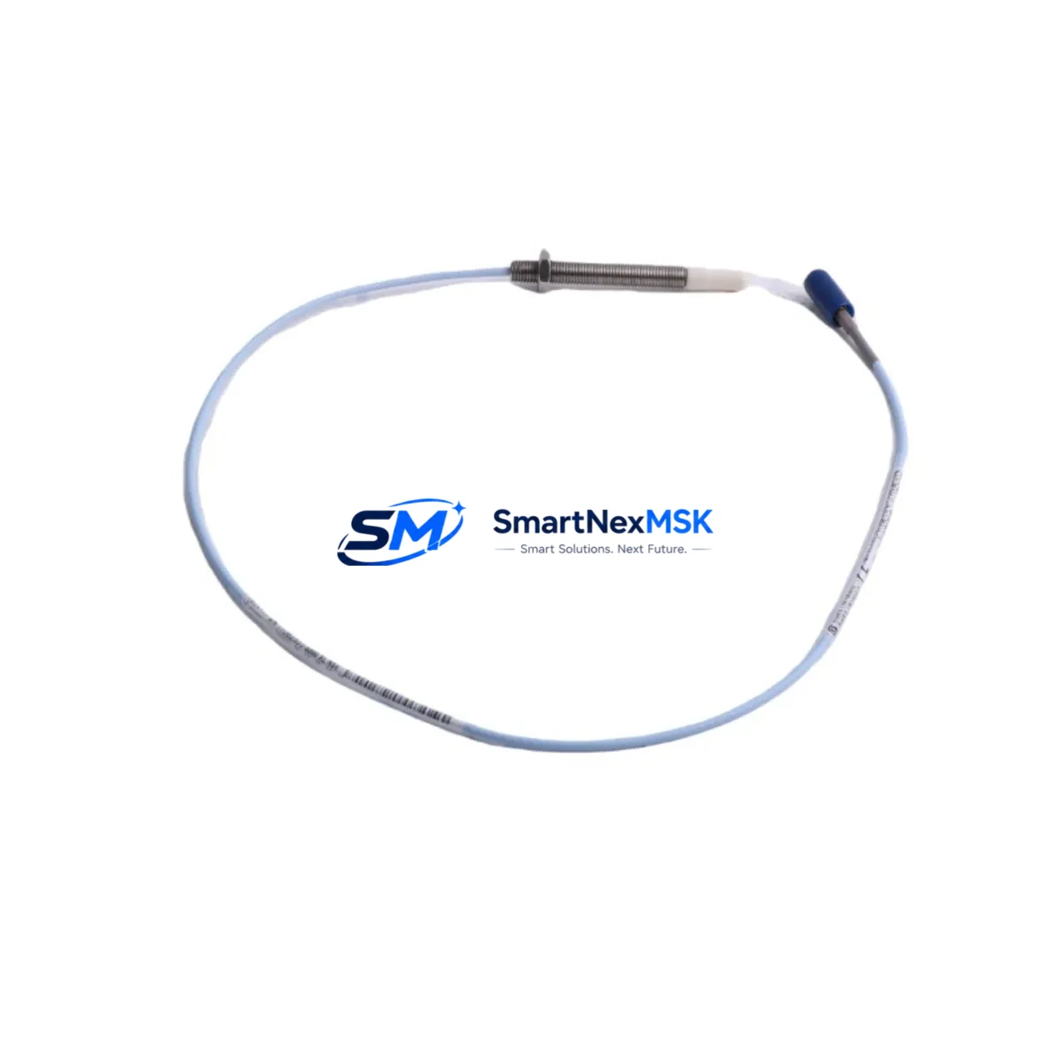
Bently Nevada 330903-00-23-10-02-00 Retrofit-Ready 8mm Proximity Transducer for 3300 XL Control Systems
The Bently Nevada 330903-00-23-10-02-00 is an 8mm proximity transducer engineered for seamless integration into legacy 3300 XL Series vibration monitoring systems. As aging machinery protection platforms approach end-of-life or face discontinued spare parts availability, this transducer serves as a verified drop-in replacement that preserves existing wiring, signal conditioning, and monitoring logic without requiring a full system overhaul. Whether you are managing a planned retrofit, responding to an unplanned failure, or building a critical spare inventory, the 330903-00-23-10-02-00 delivers the dimensional accuracy, output linearity, and environmental tolerance demanded by rotating machinery protection applications in power generation, oil and gas, petrochemical, and heavy industrial environments.
This transducer is designed to work within the complete Bently Nevada 3300 XL measurement chain. Before installation, engineers should verify power supply capacity from the existing 3300 XL proximitor or extension cable driver — typically the 330130 or 330180 series proximitor — to confirm that the 24 VDC bias voltage and current draw remain within specification. Terminal wiring at the junction box or field terminal assembly should be inspected for correct polarity, shield grounding, and cable continuity before the new transducer is energized. The coaxial extension cable connecting the transducer to the proximitor must match the original cable length and impedance to maintain calibrated gap voltage output; substituting a non-matched cable length will shift the linear range and introduce measurement error that may not be immediately apparent during bench testing.
When replacing a failed or degraded transducer in a live system, technicians should document the existing gap voltage reading at the proximitor output before removal. The target installation gap for the 330903-00-23-10-02-00 is typically set to achieve the mid-range output voltage specified in the 3300 XL system documentation, commonly near -10 VDC for standard configurations. After physical installation and gap setting, the output voltage should be verified at the 3300 XL monitor input card — such as the 3300/16 or 3300/20 series I/O modules — before the channel is returned to service. Any deviation from the expected gap voltage should be investigated at the proximitor, extension cable, and transducer connections before assuming a hardware fault.
For facilities undertaking a broader control system modernization, the 330903-00-23-10-02-00 is frequently deployed alongside other 3300 XL ecosystem components. Replacement projects often involve the 3300/55 Keyphasor module for phase reference, the 3300/46M temperature monitor for bearing RTD inputs, and the 3300/95 power supply module when the existing rack power infrastructure is being refreshed. In multi-rack installations, the 3500 rack system may be introduced as the target platform for a phased migration, and the 330903-00-23-10-02-00 transducer remains compatible with 3500 series proximitors during the transition period, allowing field sensors to remain in place while monitor hardware is upgraded rack by rack. This approach significantly reduces the scope of any single maintenance window and allows production continuity during the migration.
Communication protocol considerations are relevant when the 3300 XL monitors feed data to a distributed control system or safety instrumented system. The 4–20 mA analog outputs from the 3300 XL monitor cards interface directly with DCS I/O modules, and these signal paths remain unaffected by a transducer swap. However, if the modernization project includes migrating from hardwired analog to digital communication via Modbus RTU or the System 1 condition monitoring software platform, the transducer signal chain must be validated end-to-end after any protocol gateway or communication module is introduced. Ensuring that the 3300 XL monitor’s relay outputs and buffered transducer outputs are correctly mapped in the new communication architecture prevents alarm logic gaps during the cutover.
Upgrade Compatibility Table
| Parameter | 330903-00-23-10-02-00 (This Unit) | Notes / Retrofit Guidance |
|---|---|---|
| Transducer Diameter | 8mm | Direct fit for standard 3300 XL 8mm probe mounts |
| Compatible Proximitor | 330130, 330180 Series | Verify extension cable length matches proximitor calibration |
| Compatible Monitor Cards | 3300/16, 3300/20, 3300/25 | Confirm channel configuration before returning to service |
| Installation Gap Voltage | Approx. -10 VDC (mid-range) | Set and verify at proximitor output terminal |
| Power Supply Requirement | 24 VDC (from proximitor) | Check 3300/95 power supply capacity in rack |
| Communication Compatibility | Analog 4–20 mA, buffered output | Compatible with DCS analog I/O; verify Modbus mapping if applicable |
| Replacement for Discontinued SKUs | 330903-00-23-10-00, 330903-00-23-10-01 | Confirm suffix revision compatibility with system documentation |
| Warranty | 12 Months | Covers manufacturing defects; includes pre-shipment functional test |
Retrofit Planning for Existing Automation Systems
A successful retrofit begins well before the maintenance window opens. The first step is a full audit of the existing measurement chain: transducer model and suffix, extension cable part number and length, proximitor model, monitor card slot assignment, and the rack address configured in the 3300 XL system. This information determines whether the 330903-00-23-10-02-00 is a true drop-in replacement or whether additional components — such as a replacement 330130 proximitor, a new coaxial extension cable assembly, or a reconfigured 3300/16 monitor card — must be sourced in parallel.
In many aging installations, the extension cable insulation has degraded alongside the transducer, and replacing only the probe tip while leaving a compromised cable in place will produce intermittent faults that are difficult to diagnose under operating conditions. It is therefore common practice to replace the transducer and extension cable as a matched set. If the proximitor itself shows signs of drift — evidenced by a slowly shifting gap voltage baseline over months of trend data in System 1 or a similar condition monitoring platform — the 330180 proximitor should be included in the replacement kit to restore full measurement chain integrity.
For installations where the 3300 XL rack also houses a 3300/46M temperature monitor, a 3300/55 Keyphasor module, or relay output modules feeding the plant safety system, the retrofit plan must account for the interaction between these modules during the maintenance window. Removing power from a single rack slot may affect adjacent modules depending on the backplane configuration, and the plant safety team should be consulted before any live rack work is performed. Where a 3500 series rack is being introduced as part of a phased migration, the new rack’s I/O wiring should be pre-terminated and verified before the cutover shift to minimize the time the measurement point is offline.
Pre-shipment functional testing of the 330903-00-23-10-02-00 is performed against a calibrated target material and gap range before dispatch. Each unit ships with a test report confirming output linearity within the specified range. This documentation supports incoming inspection procedures and provides a baseline for the post-installation gap voltage verification. Units are available from stock for immediate dispatch, supporting both planned maintenance schedules and emergency breakdown situations where minimizing downtime is the primary constraint.
Downtime Control During System Migration
Minimizing downtime during a transducer replacement or broader 3300 XL system migration requires a structured approach that separates preparation work from the actual cutover. All mechanical access, cable routing, and terminal labeling should be completed during normal operations where possible, leaving only the final disconnection, installation, gap setting, and verification steps for the maintenance window itself.
Before the window opens, the existing gap voltage and vibration trend data should be exported from the 3300 XL monitor or System 1 platform to establish a pre-replacement baseline. This baseline serves two purposes: it confirms the measurement point was functional before the work began, and it provides a reference for the post-installation verification. If the vibration amplitude or gap voltage after replacement differs significantly from the pre-work baseline, the discrepancy must be investigated before the machine is returned to service.
Program logic in the associated DCS or safety system should not require modification for a like-for-like transducer replacement, as the signal output characteristics of the 330903-00-23-10-02-00 are consistent with the original 3300 XL transducer specification. However, if the replacement is part of a broader migration that introduces new monitor cards or changes the rack address of the measurement channel, the DCS tag mapping and alarm setpoints must be verified and updated before the system is returned to automatic control. HMI faceplate displays referencing the affected measurement point should be checked to confirm that the live value updates correctly after the cutover and that no stale or frozen values are being displayed.
Field commissioning should follow a defined sequence: power-on verification, gap voltage check at the proximitor output, signal verification at the monitor card input, alarm trip test at the monitor relay output, and final confirmation of the live value in the DCS or condition monitoring system. Completing this sequence in order and documenting each step provides a clear record that the replacement was performed correctly and that the measurement point is fully functional before the maintenance window is closed.
Retrofit Support FAQ
Q: Is the 330903-00-23-10-02-00 a direct replacement for earlier suffix revisions such as -00-23-10-00 or -00-23-10-01?
A: In most applications, yes. The -02-00 suffix revision reflects a manufacturing update that maintains dimensional and electrical compatibility with earlier revisions. However, you should verify against your system documentation and the original proximitor calibration data to confirm that no application-specific configuration requires a specific suffix. If in doubt, contact our technical team with your system details before ordering.
Q: What pre-shipment testing is performed on each unit?
A: Each 330903-00-23-10-02-00 undergoes functional testing against a calibrated target at the specified gap range before dispatch. Output linearity, bias voltage response, and physical dimensions are verified. A test report is included with each shipment to support your incoming inspection and installation documentation requirements. All units carry a 12-month warranty covering manufacturing defects from the date of shipment.
Q: Do I need to reconfigure the 3300 XL monitor card after replacing the transducer?
A: For a like-for-like replacement using the same SKU and extension cable length, no monitor card reconfiguration is required. The gap voltage should be set mechanically during installation and verified at the proximitor output. If you are changing the extension cable length or proximitor model as part of the replacement, the monitor card’s full-scale range and alarm setpoints should be reviewed against the new measurement chain calibration data.
Q: How quickly can units be dispatched for emergency breakdown situations?
A: Units are available from stock and can be dispatched within 24 hours for urgent requirements. Express shipping options are available to most global destinations. Contact sales@smartnexmsk.com or call +86 18259474341 to confirm availability and arrange expedited dispatch for time-critical applications.
© 2026 SMARTNEXMSK. All rights reserved.
Original Source: https://smartnexmsk.com
Contact: sales@smartnexmsk.com | +86 18259474341


