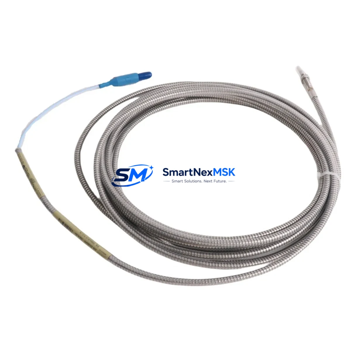
Bently Nevada 330904-00-02-10-02-05/CN Maintenance-Ready Spare for 3300 NSv Automation
The Bently Nevada 330904-00-02-10-02-05/CN is an original eddy-current proximity probe engineered for continuous vibration monitoring in rotating machinery protection systems. Designed as a direct maintenance spare for the 3300 NSv series, this probe delivers reliable shaft displacement measurement in turbines, compressors, pumps, and other critical rotating assets where unplanned downtime carries significant operational and financial risk. Maintenance engineers and procurement teams managing aging machinery protection infrastructure rely on this probe to restore system integrity quickly, minimize mean time to repair (MTTR), and sustain API 670-compliant monitoring without costly system redesigns.
Whether you are executing a planned outage, responding to a probe fault alarm, or building a strategic spare parts inventory for a multi-train facility, the 330904-00-02-10-02-05/CN provides a tested, traceable, and warranty-backed replacement that integrates directly into existing 3300 NSv monitor racks without reconfiguration.
Spare Maintenance Table
| Parameter | Specification |
|---|---|
| SKU / Part Number | 330904-00-02-10-02-05/CN |
| Brand | Bently Nevada |
| Series | 3300 NSv (Non-contact Vibration) |
| Sensor Type | Eddy-Current Proximity Probe |
| Cable Length | 7.62 m (25 ft) integral armored cable |
| Tip Diameter | 8 mm (standard) |
| Sensitivity | 7.87 V/mm (200 mV/mil) |
| Linear Range | 0.25 – 2.54 mm (10 – 100 mil) |
| Operating Temperature | -35°C to +177°C |
| Target Material Compatibility | Steel, stainless steel, Inconel (per calibration) |
| Connector | 3-pin MIL-C-5015 (CN suffix) |
| System Compatibility | 3300 NSv Monitor, 3300/16 Monitor, 3500/42M |
| Installation | Threaded probe holder, locknut torque per BN installation guide |
| Condition | Original spare, tested before shipment |
| Warranty | 12 Months |
| Origin | USA |
Maintenance Planning for Continuous Operation
When replacing the 330904-00-02-10-02-05/CN in the field, a disciplined maintenance engineer will treat the probe swap as an opportunity to audit the entire vibration monitoring loop. The probe alone does not operate in isolation — it functions as part of a signal chain that includes the 330130-080-00-00 extension cable (or equivalent 3300 NSv series extension), the 330180-X0-05 proximitor/oscillator driver module, and the 3300/16 or 3500/42M monitor card housed in the rack. Any degradation in the extension cable’s shielding or connector integrity will introduce noise that mimics probe failure, so inspecting and if necessary replacing the extension cable during the same outage window is strongly recommended.
Inside the control cabinet, verify the 3300 NSv power supply module output voltage (typically -24 VDC) is within specification before reconnecting the new probe. A marginal power supply can shorten probe service life and produce erratic gap voltage readings. If the facility runs a 3500 Series rack alongside the 3300 NSv system, confirm that the 3500/15 power supply and 3500/20 rack interface module are also in good health, as cross-system power bus issues can affect monitoring accuracy.
For facilities managing both radial vibration and axial position monitoring, the replacement outage is also the right time to inspect the paired 330905-00-02-10-02-05/CN thrust probe and its associated proximitor. Thrust and radial probes on the same shaft often experience similar wear patterns, and replacing one while leaving the other at end-of-life creates asymmetric maintenance risk. Similarly, check the 3300/55 temperature monitor inputs and any 3300/65 tachometer probes in the same cabinet, as these share the monitoring rack environment and are subject to the same thermal and vibration stresses.
For sites operating older machinery with legacy wiring, inspect terminal blocks and 3300 NSv junction boxes for corrosion, loose terminations, and insulation breakdown. A clean, low-resistance signal path from probe tip to monitor input is essential for accurate gap voltage and vibration amplitude readings. Where signal runs exceed recommended lengths, confirm that signal isolators or barriers appropriate for the hazardous area classification are in place and functioning.
Site Replacement Workflow
Step 1 — Pre-shutdown verification: Record the existing probe gap voltage (typically -10.0 to -11.0 VDC for mid-range) and vibration baseline from the 3300 NSv monitor display or DCS historian. This establishes the acceptance criterion for the replacement probe after installation.
Step 2 — Isolation and removal: De-energize the proximitor driver per site LOTO procedure. Disconnect the extension cable at the junction box. Unthread the probe from its holder using the correct spanner, noting the number of turns for reference during reinstallation.
Step 3 — Installation: Thread the 330904-00-02-10-02-05/CN into the probe holder. Set the gap to the manufacturer-specified distance (typically 1.0 mm / 40 mil for mid-range operation) using a non-ferrous feeler gauge or gap-setting tool. Torque the locknut per the Bently Nevada installation guide. Reconnect the extension cable, ensuring the MIL-C-5015 CN connector is fully seated and the coupling nut is hand-tight plus one-quarter turn.
Step 4 — Commissioning: Re-energize the proximitor. Verify gap voltage is within the linear range. Confirm vibration readings are consistent with the pre-shutdown baseline. Check for alarm or danger setpoint trips in the 3300 NSv or 3500 monitor. Document the as-left gap voltage and date in the maintenance management system.
Step 5 — System compatibility confirmation: If the replacement probe is installed in a system previously calibrated for a different target material or cable length combination, recalibrate the proximitor driver per the 3300 NSv calibration procedure to ensure measurement accuracy. This step is critical when migrating from a non-CN connector variant or a different cable length suffix.
This workflow reduces unplanned downtime, ensures system compatibility, and supports a traceable maintenance record — all of which are essential for facilities operating under API 670, ISO 13373, or equivalent machinery protection standards.
Spare Parts Support FAQ
Q1: Is the 330904-00-02-10-02-05/CN a direct drop-in replacement for other 330904 suffix variants?
The 330904 series probes share the same 8 mm tip and 3300 NSv system compatibility, but suffix codes encode cable length, connector type, and calibration target material. The -02-10-02-05/CN designates a 7.62 m cable with a CN-type MIL connector. Before substituting a different suffix, verify that the replacement probe’s cable length matches the existing extension cable and that the connector type is compatible with your junction box. If in doubt, contact our technical team with your existing probe label data for confirmation.
Q2: What does the 12-month warranty cover, and how is it validated?
All units shipped from SMARTNEXMSK carry a 12-month warranty covering manufacturing defects and functional failure under normal operating conditions. Each probe is tested for gap voltage linearity and output signal integrity before shipment. A test report is available upon request. Warranty claims require the original invoice and a description of the failure mode. Field damage caused by incorrect installation, over-torquing, or target contact is not covered.
Q3: How should I manage spare probe inventory for a multi-train facility?
Industry best practice for critical rotating machinery is to maintain a minimum of one spare probe per monitored shaft position, plus one spare proximitor driver per monitor channel type. For facilities with 10 or more monitored positions, a pooled inventory of 3–5 probes of the most common suffix variants, combined with a consignment or rapid-replenishment agreement, reduces both carrying cost and stockout risk. SMARTNEXMSK supports long-term supply agreements and can provide lead-time commitments for planned outage schedules.
Q4: Can this probe be used in hazardous area (Ex) installations?
The 330904-00-02-10-02-05/CN is designed for use with the 3300 NSv proximitor system. Hazardous area suitability depends on the complete system certification (probe + extension cable + proximitor + barrier/isolator), not the probe alone. For Ex Zone 1 or Zone 2 installations, confirm that the associated proximitor and any installed Zener barriers or galvanic isolators carry the appropriate ATEX, IECEx, or regional certification for your installation class. Contact our team for system-level compliance documentation.
© 2026 SMARTNEXMSK. All rights reserved.
Original Source: https://smartnexmsk.com
Contact: sales@smartnexmsk.com | +86 18259474341


