Bently Nevada 330904-00-06-05-01-00: Retrofit-Ready Proximity Transducer for 3300 XL Series Control Systems
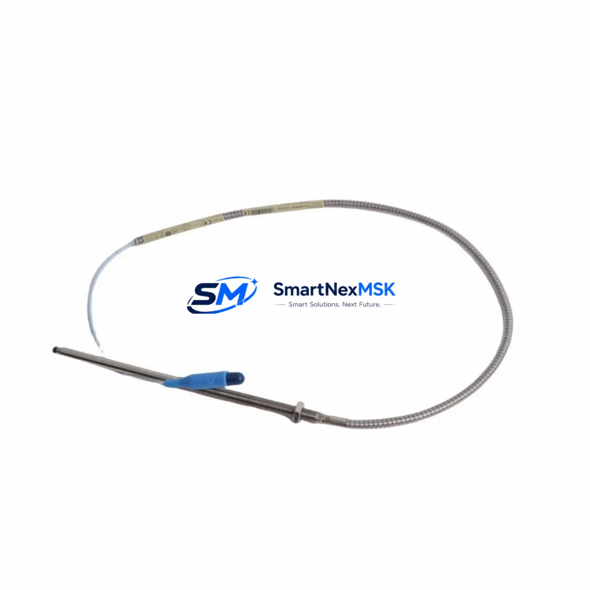
The Bently Nevada 330904-00-06-05-01-00 is a high-precision eddy-current proximity transducer engineered for the 3300 XL NSv monitoring platform. Designed as a direct retrofit replacement for legacy 3300 Series installations, this transducer delivers the same signal conditioning performance, gap voltage linearity, and mechanical form factor as the original OEM component — enabling smooth, low-risk upgrades in rotating machinery protection systems without requiring panel redesign or software re-engineering.
Industrial facilities operating gas turbines, steam turbines, compressors, pumps, and gearboxes rely on the 3300 XL NSv system for continuous vibration and position monitoring. When original transducers reach end-of-life or become obsolete, sourcing a verified replacement with confirmed compatibility is critical to maintaining system integrity and avoiding unplanned downtime. The 330904-00-06-05-01-00 meets this requirement with a 5-metre armored cable assembly, standard 8 mm probe tip, and -24 VDC bias voltage output compatible with the 3300 XL monitor rack.
Upgrade Compatibility Table
| Parameter | 330904-00-06-05-01-00 (This Unit) | Legacy 3300 Series Reference |
|---|---|---|
| Probe Tip Diameter | 8 mm | 8 mm |
| Cable Length | 5 m (armored) | 5 m standard |
| Bias Voltage Output | -24 VDC nominal | -24 VDC nominal |
| Sensitivity | 7.87 V/mm (200 mV/mil) | 7.87 V/mm (200 mV/mil) |
| Linear Range | 0.25 mm – 2.54 mm | 0.25 mm – 2.54 mm |
| Monitor Rack Compatibility | 3300 XL NSv, 3300/16, 3300/20 | 3300 XL, 3300/16 |
| Connector Type | BNC / MIL-C-26482 | BNC standard |
| Installation Requirement | Standard 3/8-24 UNF mounting thread | 3/8-24 UNF |
| Communication / Signal Protocol | Analog voltage (passive eddy-current) | Analog voltage |
| Retrofit Recommendation | Direct drop-in; no driver card change required | — |
| Commissioning Focus | Gap voltage verification, OK relay check, alert/danger setpoint confirmation | — |
| Warranty | 12 Months | — |
Retrofit Planning for Existing Automation Systems
Replacing a proximity transducer in an operating plant requires careful pre-outage planning. Before removing the legacy unit, engineers should document the existing gap voltage reading at the 3300 XL monitor card — typically measured at the OK relay terminal or the buffered output BNC connector on the front panel of the 3300/16 or 3300/20 monitor module. This baseline reading confirms the target installation gap for the new 330904-00-06-05-01-00 probe.
The 3300 XL NSv system uses a dedicated proximitor/driver, such as the 330180-X1-05 or 330130-040-00-00 series extension cable, to condition the raw eddy-current signal from the probe. During retrofit, verify that the existing extension cable length matches the replacement transducer’s system length specification — mismatched cable lengths alter the system’s linear range and sensitivity calibration. If the original extension cable is damaged or non-standard, a replacement 330130-040-00-00 or equivalent armored extension cable should be sourced simultaneously.
Terminal wiring at the junction box or marshalling cabinet should be inspected for corrosion, loose ferrules, and correct shield grounding. The 3300 XL NSv proximitor output connects to the monitor rack via a shielded twisted-pair cable terminated at the 3300/16 or 3300/20 I/O terminal block. Confirm that the shield drain wire is grounded at one end only — typically at the monitor rack — to prevent ground loops that can introduce noise into the vibration signal chain.
For facilities running a Bently Nevada System 1 condition monitoring platform, the transducer replacement does not require changes to the System 1 database configuration, provided the channel sensitivity and gap voltage parameters remain unchanged. However, if the plant is migrating from an older 3300 Series rack to a newer 3500 Series rack as part of a broader control system upgrade, the 3500/42M or 3500/40M monitor modules require re-engineering of the I/O terminal assignments and alert/danger setpoint re-entry in the 3500 Rack Configuration Software.
Control cabinet upgrades often involve simultaneous replacement of the 3300 XL power supply module, such as the 3300/05 or equivalent DC power conditioner, to ensure stable -24 VDC supply to the new transducer. Verify that the power supply’s current capacity supports all active channels in the rack, particularly when adding I/O expansion modules or upgrading from a 4-channel to an 8-channel monitor configuration. The 3300/16 monitor accepts up to 16 channels of proximity input, and each channel’s power draw must be accounted for in the rack power budget.
HMI screens connected to the DCS or SCADA system — whether running on a Honeywell Experion PKS, Emerson DeltaV, or ABB 800xA platform — display the vibration and position values derived from the 3300 XL monitor’s 4–20 mA or Modbus RTU output. After transducer replacement, confirm that the HMI trend displays update correctly and that the OK status relay output from the monitor card is reflected accurately on the operator console. Any discrepancy in the OK relay state after installation typically indicates an incorrect installation gap or a wiring fault at the proximitor terminal.
For plants using a Keyphasor module such as the 3300/25 or 3500/25, confirm that the Keyphasor signal is unaffected by the transducer swap, as phase-referenced vibration measurements depend on a stable once-per-revolution trigger. Programming cables such as the 3500/93 or a standard RS-232 to USB adapter may be required to access the monitor rack’s configuration port for setpoint verification after commissioning.
Downtime Control During System Migration
Minimizing production downtime during a proximity transducer replacement requires a structured outage window plan. The 330904-00-06-05-01-00 is a passive eddy-current device with no firmware or software configuration — the replacement procedure is purely mechanical and electrical, which significantly reduces commissioning time compared to smart transmitter or digital fieldbus device replacements.
A typical replacement sequence proceeds as follows: isolate the monitor channel by placing the 3300 XL monitor card into bypass mode (if supported) or by acknowledging the expected OK relay dropout at the DCS. Remove the legacy probe from the machinery casing, noting the thread engagement depth for reference. Install the 330904-00-06-05-01-00 to the same thread depth, then adjust the gap to achieve the target bias voltage — typically between -10 VDC and -18 VDC for most steel target materials — as measured at the buffered output of the proximitor. Reconnect the extension cable and verify the OK relay closes before releasing the bypass.
Original program logic in the DCS or safety instrumented system (SIS) does not require modification for a like-for-like transducer replacement. Alert and danger setpoints stored in the 3300 XL monitor card are retained in non-volatile memory and are not affected by power cycling during the swap. This preserves the existing protection logic and eliminates the risk of inadvertent setpoint changes during the outage.
For critical machinery where a cold outage is not acceptable, a hot-swap approach using a spare monitor channel — if available in the 3300/16 or 3300/20 rack — allows the new transducer to be commissioned on an inactive channel before cutting over, further reducing the window during which the machine operates without vibration protection. All units are pre-tested and shipped with an inspection report confirming bias voltage output and sensitivity within OEM specification.
Retrofit Support FAQ
Q1: Is the 330904-00-06-05-01-00 a direct replacement for the original Bently Nevada part?
Yes. The 330904-00-06-05-01-00 is a verified retrofit replacement for the original Bently Nevada proximity transducer of the same part number. It maintains identical probe tip diameter, cable length, sensitivity, and bias voltage output, ensuring drop-in compatibility with the 3300 XL NSv monitor rack without requiring driver card changes or system recalibration.
Q2: What wiring checks are required before installation?
Before installation, inspect the extension cable for continuity and shield integrity, verify the -24 VDC supply voltage at the proximitor input terminals, and confirm that the terminal block connections at the monitor rack are clean and torqued to specification. Ensure the cable shield is grounded at the monitor rack end only to prevent ground loop interference.
Q3: How is commissioning verified after replacement?
After mechanical installation, adjust the probe gap to achieve a bias voltage between -10 VDC and -18 VDC (for standard steel targets) at the proximitor buffered output. Confirm the OK relay on the 3300 XL monitor card closes, verify that the DCS or System 1 platform displays a valid vibration reading, and check that alert and danger setpoints are active. Document the final gap voltage and bias reading in the maintenance record.
Q4: What warranty and pre-shipment testing does this unit include?
Every 330904-00-06-05-01-00 unit is covered by a 12-month warranty from the date of shipment. Prior to dispatch, each unit undergoes functional testing including bias voltage output verification, sensitivity confirmation, and cable continuity check. A test report is available upon request. Units are packaged in anti-static, shock-protected packaging to ensure safe transit.
© 2026 SMARTNEXMSK. All rights reserved.
Original Source: https://smartnexmsk.com
Contact: sales@smartnexmsk.com | +86 18259474341


