Bently Nevada 330904-00-11-05-02-00 3300 NSv Spare: Precision Proximity Probe for Industrial Downtime Control
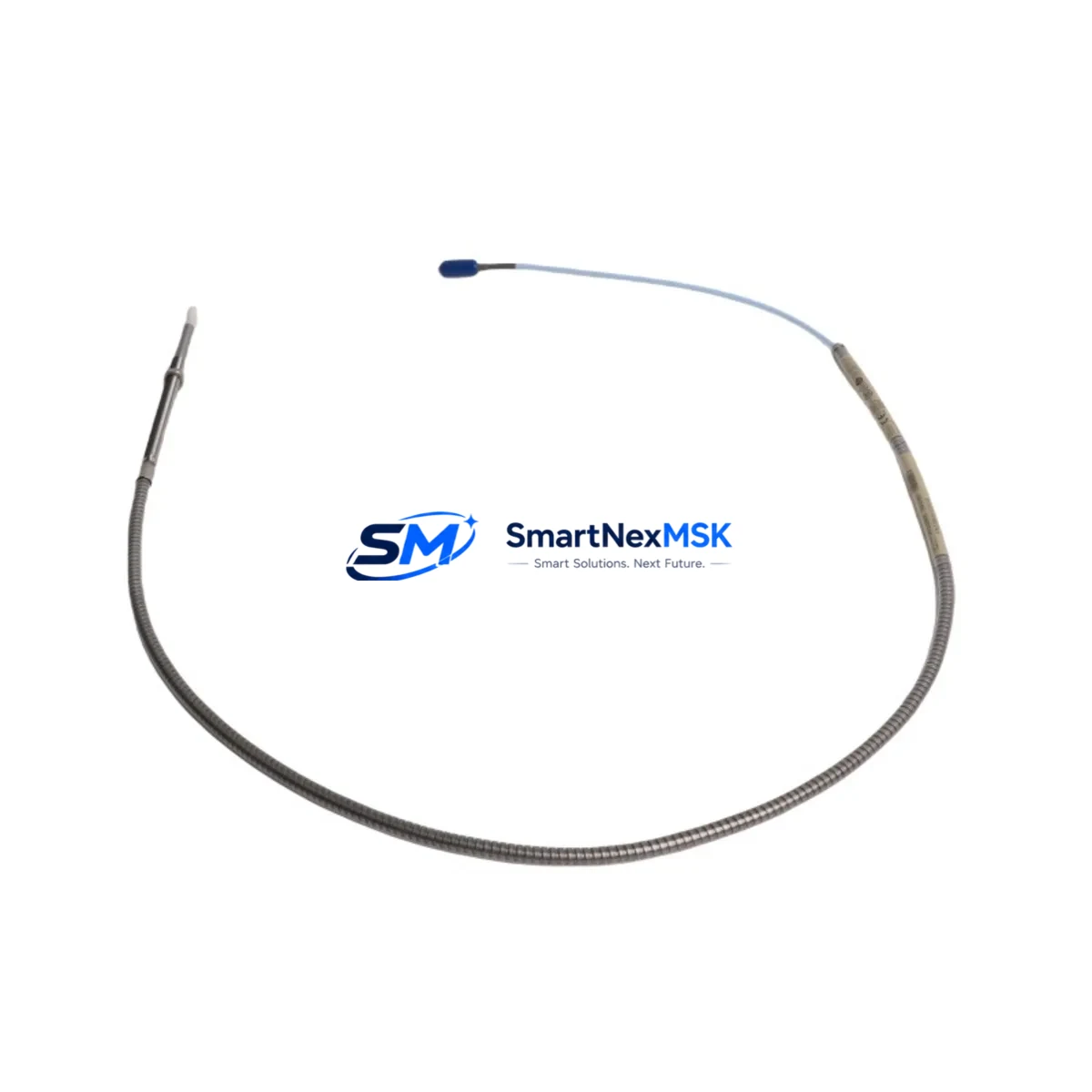
The Bently Nevada 330904-00-11-05-02-00 is an original 11mm eddy current proximity probe from the 3300 NSv series, engineered for continuous shaft vibration and position monitoring in rotating machinery. In industrial maintenance environments — from turbine control panels to compressor skids — this probe is a critical front-line sensor whose failure can trigger unplanned shutdowns, cascade protection trips, and costly production losses. Sourcing a verified, tested spare before failure occurs is the single most effective strategy for maintaining uptime in machinery protection systems.
This listing provides a maintenance-ready, original-specification replacement for the 330904-00-11-05-02-00. Each unit is inspected and function-tested prior to dispatch, backed by a 12-month warranty, and shipped with full documentation to support site acceptance testing and commissioning records.
Spare Maintenance Table
| Parameter | Specification |
|---|---|
| SKU / Part Number | 330904-00-11-05-02-00 |
| Brand | Bently Nevada |
| Series | 3300 NSv (Non-Standard Voltage) |
| Probe Type | Eddy Current Proximity Probe, 11mm |
| Cable Length | 5m (standard configuration) |
| Output Voltage Range | -2 VDC to -18 VDC (nominal) |
| Supply Voltage | -24 VDC (via Proximitor / driver) |
| Gap Range | 0.25 mm – 2.25 mm (typical) |
| Target Material Compatibility | AISI 4140 steel, carbon steel shafts |
| Connector Type | Integral coaxial, armored extension cable |
| Application Environment | Rotating machinery, turbines, compressors, pumps, motors |
| Ingress Protection | Suitable for industrial plant environments |
| Compatibility | 3300 NSv Proximitor Sensor (e.g. 330180-X1-05), 3300 XL 8mm/11mm systems |
| Installation | Threaded mounting, torque to manufacturer spec; gap set with feeler gauge or oscilloscope |
| Maintenance Recommendation | Replace probe and extension cable as a matched set; verify Proximitor output at commissioning |
| Warranty | 12 Months from date of shipment |
| Origin | USA (Original Bently Nevada manufacture) |
Maintenance Planning for Continuous Operation
When a 330904-00-11-05-02-00 proximity probe is flagged for replacement — whether during a scheduled outage, a routine vibration audit, or an emergency trip investigation — maintenance engineers should treat the event as an opportunity to inspect the entire measurement chain and surrounding protection circuit. A probe failure rarely occurs in isolation; cable degradation, connector corrosion, and Proximitor drift are common co-contributors.
Begin by inspecting the matched extension cable (typically a 330130-series or 330140-series armored coaxial cable) for jacket cracking, connector pin damage, or moisture ingress at the junction box. A compromised extension cable will produce erratic gap voltage readings even with a new probe installed. Next, verify the Proximitor sensor — commonly a 330180-X1-05 or 330180-X1-CN — for correct bias voltage output and scale factor. If the Proximitor is more than 10 years in service, proactive replacement during the same outage window eliminates a second shutdown within the same maintenance cycle.
At the rack level, inspect the 3300/16 Dual Voting Trip Module or the 3500/42M Proximitor / Seismic Monitor card for alarm setpoint drift and relay contact wear. Relay output modules — such as the 3500/32 4-Channel Relay Module — should be exercised and contact resistance verified. Terminal blocks and field wiring within the control cabinet should be torque-checked; loose terminations on signal-level circuits are a leading cause of spurious trips in vibration monitoring systems.
For plants running older 3300 XL or legacy 7200 series systems, this is also the appropriate time to assess whether the existing 3300/55 Dual Thrust Position Monitor or 3300/46M Hydro Monitor cards are still within calibration. Pairing a new probe with an out-of-calibration monitor card negates the accuracy benefit of the replacement. Where 4–20 mA output signals feed a DCS historian or safety PLC, verify signal isolators — such as a PR Electronics 3114 or equivalent DIN-rail signal conditioner — are functioning correctly and that loop resistance is within specification.
Finally, confirm that the replacement probe’s gap voltage is documented in the site maintenance log and that the as-left gap measurement is recorded for the next planned inspection interval. This supports both predictive maintenance trending and regulatory compliance for machinery protection systems in API 670-governed installations.
Site Replacement Workflow
Step 1 — Isolation and Permit: Obtain a Permit to Work (PTW) and isolate the machinery per site LOTO procedures. Do not attempt probe replacement on running equipment.
Step 2 — Record As-Found Data: Before disconnecting, record the existing gap voltage from the Proximitor output (typically measured at the field junction box or rack terminal). Note the physical gap measurement with a feeler gauge. This baseline is essential for commissioning the replacement.
Step 3 — Remove Old Probe and Extension Cable: Disconnect the extension cable at the junction box. Unthread the probe from the bracket. Inspect the mounting bracket and probe boss for corrosion or thread damage — replace if necessary to ensure correct probe positioning.
Step 4 — Install 330904-00-11-05-02-00 Replacement: Thread the new probe to the bracket. Set the initial gap to the manufacturer’s recommended starting point (typically 1.0 mm for 11mm probes on steel targets). Connect the extension cable, ensuring the coaxial connector is clean and fully seated.
Step 5 — Commission and Verify: Apply power to the Proximitor. Measure the output voltage and adjust the probe gap until the bias voltage falls within the linear range specified on the Proximitor label (typically -10 VDC ± 0.5 VDC at the nominal gap). Confirm the reading is stable with no oscillation.
Step 6 — Functional Test: Simulate a high-vibration condition (if test facilities permit) or verify alarm and trip setpoints are correctly annunciated at the monitor rack. Confirm relay outputs operate correctly before returning the machine to service.
Step 7 — Documentation: Record as-left gap voltage, physical gap, and Proximitor scale factor in the site maintenance management system (CMMS). Retain the replaced probe for failure analysis if a root cause investigation is required.
Spare Parts Support FAQ
Q1: Is the 330904-00-11-05-02-00 compatible with both 3300 NSv and 3300 XL Proximitor systems?
The 330904-00-11-05-02-00 is designed for the 3300 NSv series. While the physical form factor is similar to 3300 XL probes, the scale factor and output characteristics differ. Always verify the Proximitor model number on your rack card before ordering. If your system uses a 3300 XL Proximitor (e.g., 330180-X1-CN), confirm compatibility with your instrumentation engineer or contact us with your full system configuration for verification.
Q2: What is included in the 12-month warranty, and what does the pre-shipment test cover?
Every 330904-00-11-05-02-00 unit is bench-tested for correct bias voltage output, scale factor linearity, and connector integrity before dispatch. The 12-month warranty covers manufacturing defects and functional failure under normal operating conditions. It does not cover physical damage caused by incorrect installation, over-torquing, or exposure to conditions outside the rated specification. A test report is available upon request.
Q3: How should I manage spare probe inventory for a multi-machine plant?
For plants with 4 or more monitored machines, we recommend maintaining a minimum of two 330904-00-11-05-02-00 probes in bonded stores, along with at least one matched extension cable set and one spare Proximitor sensor. This covers a single emergency replacement plus one planned outage without requiring expedited procurement. For critical turbine or compressor trains, consider a complete channel spare kit including the monitor card and relay module.
Q4: Can this probe replace older discontinued Bently Nevada part numbers?
The 330904-00-11-05-02-00 supersedes several earlier 3300 series probe configurations. If you are replacing a probe from a legacy 7200 or early 3300 system, provide your existing part number and Proximitor model to our technical team for a compatibility cross-reference before ordering. Substituting an incompatible probe without verifying scale factor can result in incorrect vibration readings and potential machinery protection gaps.
© 2026 SMARTNEXMSK. All rights reserved.
Original Source: https://smartnexmsk.com
Contact: sales@smartnexmsk.com | +86 18259474341


