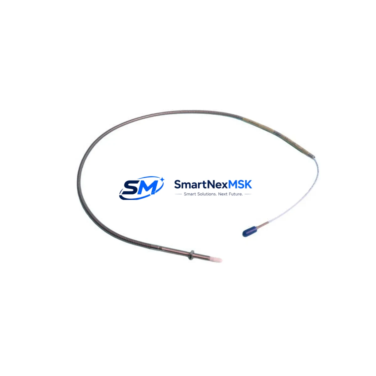
Bently Nevada 330904-00-12-05-01-00 Retrofit-Ready Proximity Transducer for 3300 XL Control Systems
The Bently Nevada 330904-00-12-05-01-00 is a high-precision eddy-current proximity transducer engineered for the 3300 XL NSv series vibration monitoring platform. As legacy rotating machinery protection systems reach end-of-service life, this module serves as the primary retrofit solution for facilities seeking to maintain continuous shaft vibration and position measurement without replacing the entire monitoring rack. Whether you are upgrading a turbine protection panel, modernizing a compressor train monitoring cabinet, or restoring a discontinued spare, the 330904-00-12-05-01-00 delivers verified electrical and mechanical compatibility with existing 3300 XL field wiring, extension cables, and signal conditioning modules.
This transducer operates on the standard Bently Nevada 3300 XL signal chain: the probe tip generates a high-frequency electromagnetic field, and gap voltage is conditioned through a compatible 3300 XL NSv proximitor extension driver — such as the 330130-045-00-00 or 330130-080-00-00 extension cable assemblies — before reaching the 3500/40M or 3500/42M monitor cards in the 3500 rack. Facilities currently running the older 3300/16 or 3300/55 series can use this transducer as part of a phased migration path, retaining existing conduit runs and terminal block wiring while upgrading the sensing element and driver electronics to current NSv specifications.
Upgrade Compatibility Table
| Parameter | 330904-00-12-05-01-00 (This Unit) | Legacy 3300/16 Probe | Notes |
|---|---|---|---|
| Series Compatibility | 3300 XL NSv | 3300/16, 3300/55 | NSv driver required for XL series |
| Tip Diameter | 5 mm (standard) | 5 mm | Direct mechanical fit in existing probe holders |
| Cable Length | 1.2 m integral cable | Varies | Pair with 330130 extension cable for rack distance |
| Target Material | Steel / Inconel | Steel / Inconel | Verify shaft material before calibration |
| Output Signal | –24 VDC nominal gap voltage | –24 VDC | Compatible with 3500/40M and 3500/42M monitor cards |
| Installation | Threaded probe holder, standard M8 thread | M8 thread | No bracket modification required |
| Communication | Analog (4–20 mA via monitor card) | Analog | Monitor card handles protocol conversion to DCS/PLC |
| Replacement Recommendation | Direct drop-in for NSv-compatible installations | Requires NSv driver upgrade | Replace extension cable if >5 years old |
| Commissioning Focus | Gap voltage calibration, OK relay verification | Recalibration required | Use Bently Nevada calibration fixture or field meter |
| Warranty | 12-Month Warranty — covers manufacturing defects and signal performance | Supplied by SMARTNEXMSK | |
Retrofit Planning for Existing Automation Systems
Successful integration of the 330904-00-12-05-01-00 into an operating plant begins well before the maintenance window opens. The first step is a rack audit of the existing 3500 series chassis: confirm that the 3500/20 rack power supply module is delivering stable ±24 VDC and ±5 VDC rails, as voltage sag under load is a common cause of false OK relay trips after transducer replacement. If the rack is running multiple 3500/40M radial vibration monitor cards alongside 3500/42M thrust position cards, verify that the backplane slot assignments and channel-to-machine-train mapping in the System 1 configuration database match the physical wiring before pulling the old probe.
Terminal block wiring at the junction box is the next critical checkpoint. The 330904-00-12-05-01-00 uses a standard three-conductor shielded cable (shield, center conductor, outer conductor) that terminates at the proximitor driver — typically a 330180-X1-05 or 330180-X1-08 NSv driver mounted in the field enclosure. Confirm that the existing 330130 series extension cable is within its rated length for the chosen driver, as exceeding the cable length specification shifts the linear range and invalidates the –24 VDC gap calibration. If the extension cable is original to the installation and more than five years old, replacing it alongside the probe is strongly recommended to avoid intermittent signal faults during the first weeks of operation.
For facilities migrating from a legacy Bently Nevada 3300/16 system to the 3300 XL NSv platform, the driver electronics must also be upgraded. The older 3300/16 proximitor is not electrically interchangeable with the NSv driver, and mixing components from the two generations will produce out-of-range gap voltages that trigger the 3500 monitor card’s danger alarm. In these cases, the retrofit bill of materials typically includes the 330904-00-12-05-01-00 probe, a matched NSv extension cable, the 330180 NSv driver, and updated System 1 channel configuration files. HMI faceplate updates in the DCS — whether running on a Honeywell Experion PKS, Emerson DeltaV, or ABB 800xA platform — should be scheduled to reflect the new channel tag names and alarm setpoints before the system is returned to service.
I/O mapping at the PLC or safety system level also requires attention. If the 3500 monitor card outputs a 4–20 mA signal to a Rockwell Automation ControlLogix or CompactLogix analog input module, verify that the input scaling in the ladder logic or function block program matches the transducer’s sensitivity specification (typically 7.87 V/mm or 200 mV/mil). Incorrect scaling will cause the historian and alarm management system to display erroneous vibration amplitude values without triggering any hardware fault, making the error difficult to detect during post-commissioning review.
Downtime Control During System Migration
Minimizing unplanned downtime during a proximity transducer replacement requires a structured pre-outage preparation protocol. Before the maintenance window, export the current System 1 configuration database and save a backup of the 3500 rack’s non-volatile memory using the Rack Configuration Software. This preserves all channel setpoints, alarm thresholds, OK relay logic, and Keyphasor assignments so that if the replacement introduces an unexpected configuration conflict, the original state can be restored within minutes rather than hours.
During the physical swap, keep the 3500 rack powered and in monitor mode where process safety permits. The 3500/40M and 3500/42M cards support channel-by-channel bypass, allowing the affected channel to be placed in bypass while adjacent channels continue to protect the machine train. This approach eliminates the need to take the entire protection system offline and maintains SIL-rated protection on all non-affected measurement points throughout the replacement procedure.
After installing the 330904-00-12-05-01-00 and reconnecting the extension cable and NSv driver, perform a static gap calibration before releasing the bypass. Set the probe gap to the midpoint of the linear range (typically 1.0–1.5 mm for a 5 mm tip probe on a steel target), verify that the gap voltage reads within ±0.5 VDC of the nominal –12 VDC midpoint value, and confirm that the OK relay is energized. Only after these checks pass should the channel bypass be released and the machine returned to normal monitoring. Document the as-found and as-left gap voltages in the maintenance management system to establish a baseline for future condition trending.
Retrofit Support FAQ
Q1: Is the 330904-00-12-05-01-00 a direct replacement for the older 3300/16 proximity probe?
The 330904-00-12-05-01-00 is mechanically compatible with standard M8 probe holders used in 3300/16 installations, but it requires an NSv-series proximitor driver (330180 series) rather than the older 3300/16 driver. If you are upgrading from the 3300/16 platform, the driver and extension cable must also be replaced. The 3500 monitor card configuration will need to be updated to reflect the NSv sensitivity specification.
Q2: What commissioning checks are required after installation?
After physical installation, perform a static gap calibration to verify the –24 VDC linear range, confirm OK relay energization, check the 4–20 mA output scaling at the receiving PLC or DCS analog input, and review System 1 channel status for any latched alarms. A short-duration coast-down or bump test is recommended to verify dynamic signal quality before returning the machine to full-load operation.
Q3: Can this transducer be used with Modbus or PROFIBUS-connected monitor cards?
The 330904-00-12-05-01-00 itself outputs an analog gap voltage signal; protocol conversion to Modbus RTU, PROFIBUS DP, or OPC-UA is handled by the 3500 monitor card and its associated communication gateway module (such as the 3500/92 communication gateway). Ensure the gateway firmware is current and that the register map in your DCS or SCADA system is updated if channel assignments change during the retrofit.
Q4: What does the 12-month warranty cover, and how is it processed?
All units supplied by SMARTNEXMSK carry a 12-month warranty covering manufacturing defects, signal performance outside published specifications, and connector integrity. Warranty claims are initiated by contacting sales@smartnexmsk.com with the order reference, installation date, and a description of the observed fault. Units are inspected and, where confirmed defective, replaced or credited within the warranty period. Warranty does not cover damage resulting from incorrect gap setting, cable length exceedance, or installation in environments outside the rated temperature and EMI specifications.
© 2026 SMARTNEXMSK. All rights reserved.
Original Source: https://smartnexmsk.com
Contact: sales@smartnexmsk.com | +86 18259474341


