Bently Nevada 330904-00-15-05-02-00 Maintenance-Ready Spare for 3300 NSv Automation
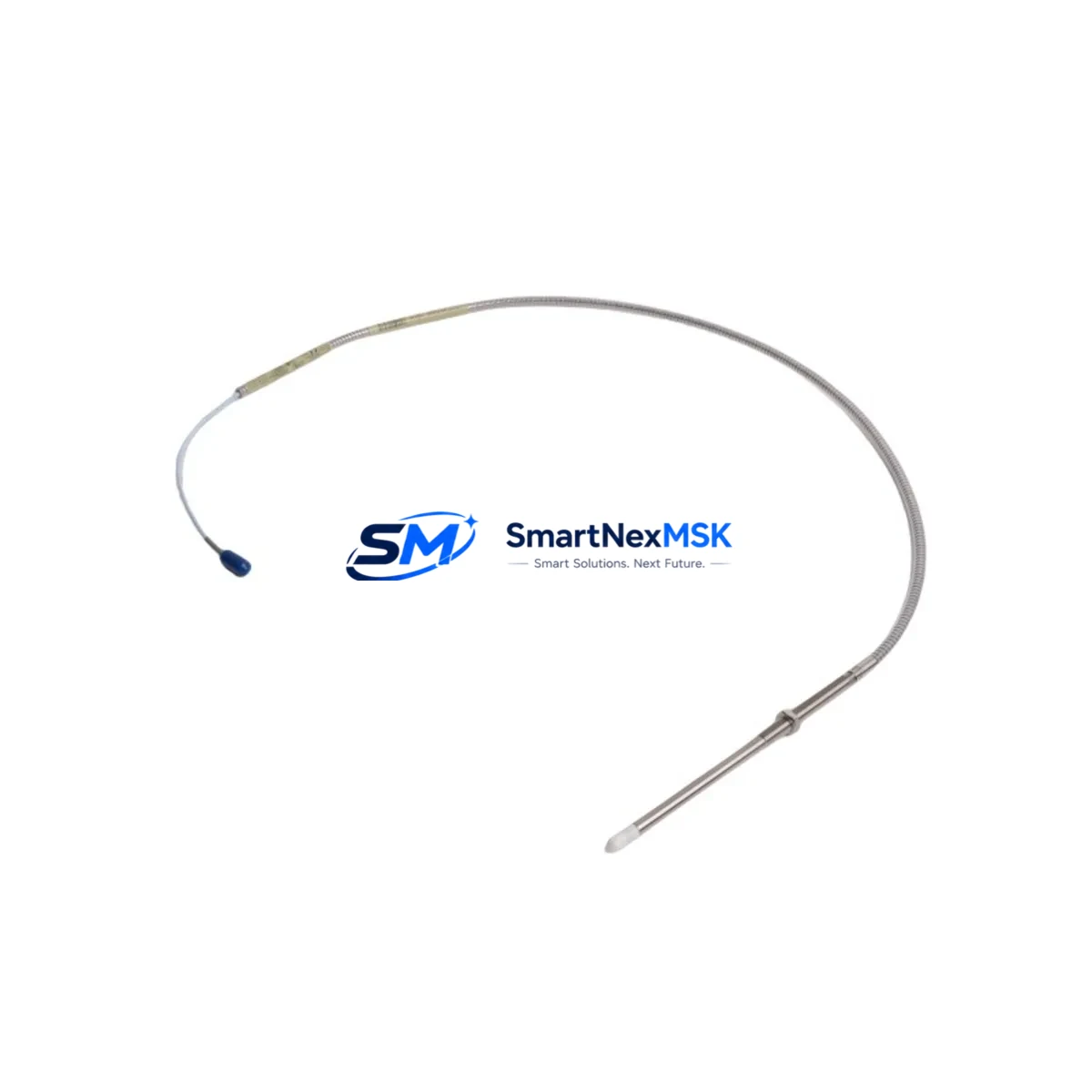
The Bently Nevada 330904-00-15-05-02-00 is an original eddy-current proximity probe from the 3300 NSv Series, engineered for continuous shaft vibration and position monitoring in rotating machinery applications. As a maintenance-ready spare, this probe is a critical component in turbine protection systems, compressor trains, pump monitoring panels, and generator bearing surveillance circuits. Holding verified stock of the 330904-00-15-05-02-00 eliminates unplanned downtime caused by probe degradation, cable fatigue, or connector corrosion — failures that can escalate into full machinery trips within minutes.
For maintenance engineers managing aging 3300 NSv monitoring systems, the 330904-00-15-05-02-00 represents a direct, plug-compatible replacement that preserves calibration integrity and system certification. For procurement engineers, sourcing this part from a verified supplier with a 12-month warranty and pre-shipment electrical testing ensures that the spare entering your storeroom is ready for immediate deployment — not a source of additional troubleshooting.
Every unit shipped by SMARTNEXMSK undergoes functional verification against Bently Nevada factory specifications before dispatch. Long-term supply continuity is supported for both single-unit emergency orders and scheduled bulk procurement for planned maintenance outages.
Spare Maintenance Table
| Parameter | Specification |
|---|---|
| Part Number | 330904-00-15-05-02-00 |
| Brand | Bently Nevada |
| Series | 3300 NSv (Non-Standard Voltage) |
| Product Type | Eddy-Current Proximity Probe |
| Probe Length | 15 cm (5.9 in) — encoded in SKU segment “-15-“ |
| Cable Length | 5 m (16.4 ft) — encoded in SKU segment “-05-“ |
| Connector Type | 02 — standard Bently Nevada coaxial connector |
| Sensing Range | Typically 0–2.54 mm (0–100 mil) linear range |
| Output Signal | Voltage proportional to gap distance (NSv output) |
| Target Material Compatibility | Steel, stainless steel, Inconel rotating shafts |
| Operating Temperature | –35°C to +120°C (probe body) |
| Application | Radial vibration, axial position, differential expansion monitoring |
| System Compatibility | Bently Nevada 3300 Series monitors, 3500 Series (with adapter), System 1 software |
| Installation | Threaded probe tip, locknut mounting, coaxial cable routing |
| Origin | USA (Bently Nevada / Baker Hughes) |
| Warranty | 12 Months — SMARTNEXMSK Verified |
| Pre-Shipment Test | Electrical continuity, gap sensitivity, output linearity verified |
| Lead Time | In-stock: ships within 2 business days |
Maintenance Planning for Continuous Operation
When replacing the 330904-00-15-05-02-00 proximity probe during a planned or emergency maintenance window, a disciplined inspection of the surrounding monitoring circuit is essential to prevent repeat failures and ensure the replacement probe performs to specification from the first startup.
Begin with the 3300 XL 8mm Extension Cable (typically 330130-series) that connects the probe to the proximitor. Extension cable connectors are a common failure point — corrosion, mechanical stress, or improper torque on the BNC-style coaxial connector can introduce signal noise that mimics probe failure. Replace the extension cable if it shows any jacket cracking, connector play, or measured resistance deviation.
Next, inspect the 3300 NSv Proximitor Sensor (such as the 330180-series or 330190-series) mounted in the junction box or control cabinet. The proximitor converts the probe’s impedance change into a calibrated voltage output. A degraded proximitor can cause erratic readings even with a new probe installed — verify its output voltage at the known gap distance before closing out the work order.
Check the 3300 Series Monitor Module (e.g., 3300/16 or 3300/20 dual-channel vibration monitor) for alarm setpoint integrity and channel configuration. After probe replacement, confirm that the OK relay output is healthy and that the vibration channel is not latched in a trip state from the prior fault event.
Inspect the terminal strip and field wiring within the machinery protection panel. Loose terminations on the signal pair or shield drain wire introduce common-mode noise that degrades the probe’s dynamic measurement accuracy. Torque all terminals to specification and verify shield continuity to the proximitor chassis ground.
If the machine is part of a turbine or compressor protection system, also verify the 3500 Series Rack (if the 3300 feeds into a 3500/42M or 3500/45 monitor via signal conditioning) for correct scale factor configuration matching the 330904-00-15-05-02-00 probe’s sensitivity. A scale factor mismatch will produce incorrect engineering unit readings in System 1 condition monitoring software without triggering any hardware fault.
For machines with both radial and axial monitoring, cross-check the companion 330500-series thrust position probe and its proximitor during the same maintenance window. Axial probes share the same cable routing and junction box environment — if one probe has degraded, the other is likely under similar stress.
Finally, review the power supply module feeding the proximitor (typically –24 VDC regulated). Voltage sag or ripple on the proximitor supply rail directly affects output accuracy. A dedicated 3300 Power Supply or equivalent DIN-rail 24 VDC unit should be load-tested and its output voltage confirmed within ±0.5 V of nominal before the machine is returned to service.
Site Replacement Workflow
Step 1 — Isolation and Permit: Obtain a machinery isolation permit. De-energize the proximitor supply at the panel terminal block, not at the monitor, to preserve monitor configuration and alarm history logs in System 1.
Step 2 — Probe Removal: Loosen the locknut and unthread the 330904-00-15-05-02-00 probe from the bracket. Note the gap distance setting (typically 1.0–1.5 mm for steel shafts) using a feeler gauge or the original commissioning record before removal.
Step 3 — Cable Inspection: Disconnect the extension cable at both ends. Inspect the coaxial connector pins and the cable jacket along its full routed length. Replace the extension cable if any damage is found — do not reuse a suspect cable with a new probe.
Step 4 — New Probe Installation: Thread the replacement 330904-00-15-05-02-00 into the bracket. Set the gap to the recorded commissioning value using a feeler gauge. Tighten the locknut to the specified torque (typically 2.5–3.0 N·m). Reconnect the extension cable with correct torque on the coaxial connector.
Step 5 — Energize and Verify: Re-energize the proximitor supply. Measure the DC output voltage at the monitor input terminals. At the set gap, the NSv output should fall within the linear range specified in the 3300 NSv calibration curve. Confirm the OK relay is energized and the channel reads a stable, noise-free value in System 1.
Step 6 — Documentation: Record the new probe serial number, installation date, gap setting, and measured output voltage in the equipment maintenance log. Update the spare parts inventory to reflect consumption and initiate a reorder for the next replacement unit.
This workflow is compatible with both direct 3300 Series monitor installations and hybrid configurations where the 3300 NSv probe feeds into a 3500 Series rack via signal conditioning adapters. The 330904-00-15-05-02-00 is a drop-in replacement for earlier 330900-series probes of the same physical configuration, reducing the need for bracket modification or recalibration in most legacy installations.
Spare Parts Support FAQ
Q1: Is the 330904-00-15-05-02-00 compatible with both 3300 and 3500 Series Bently Nevada systems?
The 330904-00-15-05-02-00 is natively designed for the 3300 NSv monitoring system. It can interface with 3500 Series monitors when used with the appropriate signal conditioning module or adapter that matches the NSv output scale factor. Always verify the scale factor configuration in the 3500 monitor channel before commissioning the replacement probe.
Q2: What pre-shipment testing does SMARTNEXMSK perform on this probe?
Each 330904-00-15-05-02-00 unit undergoes electrical continuity verification, coaxial connector integrity check, and output linearity confirmation against the Bently Nevada 3300 NSv calibration standard before dispatch. A test record is available upon request. The 12-month warranty covers functional failure under normal operating conditions from the date of shipment.
Q3: How should this probe be stored as a long-term spare?
Store the 330904-00-15-05-02-00 in its original packaging or an anti-static, moisture-controlled environment at 15–30°C. Protect the coaxial connector with the supplied dust cap. Inspect the probe annually for connector corrosion or cable jacket degradation. Probes stored correctly retain full functionality for 5+ years, making them suitable for long-cycle maintenance programs and old-system life extension strategies.
Q4: Can SMARTNEXMSK supply multiple units for a planned outage or bulk spare inventory program?
Yes. SMARTNEXMSK supports both emergency single-unit orders and bulk procurement for scheduled turnarounds. Volume pricing and priority allocation are available for maintenance contracts. Contact our team with your required quantity and delivery schedule to confirm availability and lead time for your specific outage window.
© 2026 SMARTNEXMSK. All rights reserved.
Original Source: https://smartnexmsk.com
Contact: sales@smartnexmsk.com | +86 18259474341


