Bently Nevada 330904-00-18-05-01-00 Retrofit-Ready Proximity Transducer for 3300 XL NSv Control Systems
The Bently Nevada 330904-00-18-05-01-00 is a high-precision eddy-current proximity transducer engineered for the 3300 XL NSv monitoring platform. Designed to deliver reliable shaft vibration, position, and speed measurements in rotating machinery applications, this unit is a direct retrofit replacement for legacy 3300 Series transducers that have reached end-of-life or are no longer available through standard supply channels. Whether you are upgrading an aging turbine protection system, restoring a compressor monitoring loop, or replacing a failed sensor in a critical production environment, the 330904-00-18-05-01-00 provides a verified, drop-in compatible solution with minimal re-engineering required.
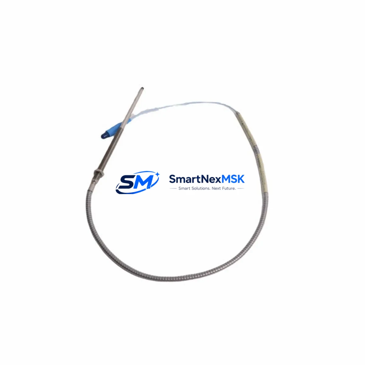
This transducer operates within the 3300 XL NSv signal conditioning architecture, maintaining full compatibility with the 3300 XL 8mm Extension Cable assemblies and the 3300 XL Proximitor Sensor driver electronics. The 18-inch (457 mm) armored cable configuration suits installations where the probe must be routed through tight machinery housings or across short distances to the proximitor mounting location. The 5 mm probe tip diameter and standard 5/16-28 UNF thread allow direct installation into existing probe holders without machining modifications, significantly reducing downtime during planned maintenance windows or emergency replacements.
When retrofitting the 330904-00-18-05-01-00 into an existing 3300 Series monitoring rack, engineers should verify the following before energizing the loop: confirm that the installed Proximitor Sensor — typically a 3300 XL 8mm Proximitor such as the 330180-91-00 or 330180-51-00 — is calibrated for the target gap voltage range (typically -10 VDC at 2.0 mm gap); inspect the extension cable connector for corrosion or mechanical damage, particularly on installations using the 330130-080-00-00 or 330130-040-00-00 cable assemblies; and validate that the 3300 XL Rack power supply module is delivering stable -24 VDC to the transducer loop. Any deviation in supply voltage will shift the output scale factor and introduce measurement error into the vibration monitor.
For systems integrated with a 3500 Series Machinery Protection System rack, the 330904-00-18-05-01-00 can be used as a field-side replacement while retaining the existing 3500/42M Proximitor I/O Module and 3500/22M Transient Data Interface. No firmware changes are required at the rack level, but the channel configuration in the System 1 Evolution software should be reviewed to confirm that the probe scale factor (typically 7.87 V/mm or 200 mV/mil) matches the replacement transducer’s calibration certificate. This step is critical when migrating from an older 7200 Series transducer to the 3300 XL NSv platform, as scale factor mismatches will cause false alarm conditions on the 3500 rack’s OK relay outputs.
In control cabinet upgrade projects where the monitoring system is being migrated from a legacy Bently Nevada 3300 rack to a modern 3500 or System 1 architecture, the 330904-00-18-05-01-00 serves as the field-side anchor point that remains unchanged while the rack electronics are replaced. This approach protects the existing probe installation investment, avoids costly re-machining of bearing housings, and allows the upgrade to proceed without removing the machine from service for extended periods. The transducer’s NSv (Non-Standard Voltage) output characteristic is fully supported by the 3500/42M I/O module when configured in the appropriate input mode.
Communication protocol migration is another common scenario where this transducer plays a key role. As plants transition from hardwired 4–20 mA vibration signals to digital Modbus RTU or OPC-UA data paths via the System 1 Evolution gateway, the physical transducer layer remains unchanged. The 330904-00-18-05-01-00 continues to deliver its analog voltage output to the proximitor, which feeds the rack’s I/O module, which in turn provides the digital data stream to the plant DCS or historian. No changes to the transducer wiring or probe gap setting are required during this protocol migration, making it one of the lowest-risk elements of the overall system modernization.
Upgrade Compatibility Table
| Parameter | 330904-00-18-05-01-00 (This Unit) | Legacy / Replaced Models |
|---|---|---|
| Series | 3300 XL NSv | 3300, 7200 Series |
| Probe Tip Diameter | 5 mm (8 mm body) | 5 mm / 8 mm |
| Cable Length | 18 inches (457 mm) | Varies (verify before ordering) |
| Thread | 5/16-28 UNF | 5/16-28 UNF (compatible) |
| Output Scale Factor | 7.87 V/mm (200 mV/mil) | Confirm against proximitor calibration |
| Supply Voltage | -24 VDC (from Proximitor) | -24 VDC |
| Compatible Proximitor | 330180-91-00, 330180-51-00 | 3300 XL 8mm Proximitor family |
| Compatible Extension Cable | 330130-080-00-00, 330130-040-00-00 | 3300 XL Extension Cable series |
| Rack Compatibility | 3500/42M, 3500/22M, 3300 Rack | 3300, 3500 Series racks |
| Installation Modification | None required | Direct drop-in replacement |
| Commissioning Requirement | Gap voltage verification, scale factor check | Standard 3300 XL commissioning procedure |
| Warranty | 12 Months | — |
Retrofit Planning for Existing Automation Systems
A successful retrofit begins well before the replacement transducer arrives on site. The engineering team should pull the existing loop documentation — including the original Bently Nevada installation drawing, the proximitor wiring diagram, and the rack channel configuration printout from System 1 Evolution or the legacy 3300 rack configurator — and cross-reference these against the 330904-00-18-05-01-00 datasheet to confirm dimensional and electrical compatibility.
The physical installation sequence typically involves: isolating the affected monitoring channel at the 3500/42M Proximitor I/O Module or 3300 rack terminal block; disconnecting the extension cable from the existing probe; removing the probe from the bearing housing using the appropriate probe wrench; installing the 330904-00-18-05-01-00 to the same thread depth (gap setting); reconnecting the 330130-080-00-00 or equivalent extension cable; and restoring power to the proximitor loop. The gap voltage should then be measured at the proximitor output terminals using a calibrated digital multimeter and adjusted to the target value specified in the machine’s vibration monitoring specification — typically between -9.5 VDC and -10.5 VDC at the nominal air gap.
For installations where the 3300 XL 8mm Proximitor Sensor (330180-91-00) is also being replaced as part of a broader system refresh, the new proximitor and transducer should be calibrated together as a matched set using the Bently Nevada calibration fixture before installation. This ensures that the combined system accuracy meets the API 670 requirements for machinery protection systems. If the 3500/22M Transient Data Interface is present in the rack, the channel’s OK status should be verified in the System 1 software after commissioning to confirm that the new transducer is within the valid measurement range.
In multi-channel installations — such as a turbine with four radial vibration probes, two axial position probes, and a keyphasor — it is common to replace all probes of the same model simultaneously to maintain consistent measurement characteristics across the machine train. In this scenario, the 330904-00-18-05-01-00 would be ordered in the required quantity, and the commissioning team would work through each channel systematically, verifying gap voltage and OK status before moving to the next. The 3500 rack’s channel inhibit function can be used to suppress alarms on channels being worked on without affecting the protection status of the remaining channels.
Downtime Control During System Migration
Minimizing unplanned downtime is the primary concern for any maintenance team replacing proximity transducers on operating machinery. The 330904-00-18-05-01-00’s direct mechanical and electrical compatibility with the existing 3300 XL NSv infrastructure means that the replacement can typically be completed within a single planned maintenance window — often less than two hours per channel for an experienced technician.
The recommended approach is to use the 3500 rack’s channel bypass or inhibit function to suppress the affected channel’s alarm and trip outputs before beginning work. This prevents a nuisance trip during the probe swap while keeping the remaining protection channels active. The original program logic in the 3500 rack — including the alarm setpoints, time delays, and trip multiply settings configured via the Rack Configuration Software — does not need to be modified. The replacement transducer uses the same signal conditioning path, so the existing configuration remains valid after the swap.
For HMI systems connected to the machinery protection rack — whether a Bently Nevada System 1 Evolution workstation, a Yokogawa CENTUM VP DCS faceplate, or a third-party SCADA display — no screen modifications are required. The channel tag names, engineering unit scaling, and alarm annunciation logic remain unchanged because the replacement transducer delivers the same signal format as the original. This is a significant advantage over platform migrations that require HMI re-engineering, which can extend the outage window by days or weeks.
After the replacement transducer is installed and the gap voltage is verified, the channel inhibit should be removed and the channel’s OK status confirmed in the System 1 software or at the 3500 rack front panel. A short observation period — typically 15 to 30 minutes at normal operating speed — is recommended to confirm that the vibration readings are stable and consistent with the adjacent channels before returning the machine to full load. All commissioning steps, gap voltage readings, and OK status confirmations should be documented in the plant’s maintenance management system for future reference and audit compliance.
Retrofit Support FAQ
Q1: Is the 330904-00-18-05-01-00 a direct replacement for older 3300 Series proximity transducers?
A: Yes. The 330904-00-18-05-01-00 is mechanically and electrically compatible with the 3300 XL NSv platform and serves as a verified replacement for legacy 3300 Series probes of the same probe tip diameter and cable length. The 5/16-28 UNF thread and 5 mm probe tip allow direct installation into existing probe holders. Gap voltage and scale factor should be verified after installation per standard 3300 XL commissioning procedures.
Q2: Do I need to reconfigure the 3500 rack or System 1 software after replacing the transducer?
A: In most cases, no. If the replacement transducer has the same scale factor (7.87 V/mm / 200 mV/mil) as the original, the existing rack channel configuration and System 1 database remain valid. The only required step is to verify the gap voltage at the proximitor output terminals and confirm the channel OK status after installation. If migrating from a 7200 Series transducer, the scale factor must be confirmed and the rack channel reconfigured if different.
Q3: What wiring changes are required during installation?
A: No wiring changes are required at the rack terminal block or junction box. The 330904-00-18-05-01-00 connects to the existing 3300 XL Extension Cable (such as the 330130-080-00-00) using the standard Bently Nevada coaxial connector. The extension cable connects to the 3300 XL 8mm Proximitor Sensor, which in turn connects to the 3500/42M I/O Module terminal block using the existing field wiring. No new cables or adapters are needed for a like-for-like replacement.
Q4: What does the 12-month warranty cover, and is pre-shipment testing performed?
A: Every 330904-00-18-05-01-00 unit is functionally tested before shipment to verify output voltage, scale factor, and mechanical integrity. The 12-month warranty covers defects in materials and workmanship under normal operating conditions. Units are shipped with a test report confirming key electrical parameters. In the event of a warranty claim, replacement units are dispatched from stock to minimize your system downtime.
© 2026 SMARTNEXMSK. All rights reserved.
Original Source: https://smartnexmsk.com
Contact: sales@smartnexmsk.com | +86 18259474341


