Bently Nevada 330904-00-20-05-01-00 Retrofit-Ready Proximity Transducer for 3300 XL Control Systems: Compatible Modernization and Smooth Legacy System Upgrade
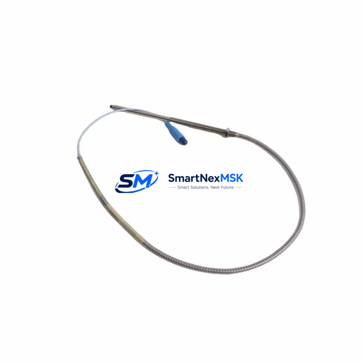
The Bently Nevada 330904-00-20-05-01-00 is a 5mm proximity transducer designed for the 3300 XL NSv (Non-contact Speed and Vibration) monitoring platform. As legacy Bently Nevada 3300 series installations age and OEM support windows narrow, plant engineers and reliability teams increasingly rely on verified retrofit-ready replacements to maintain continuous machinery protection without triggering full system overhauls. This unit delivers a direct, drop-in compatible solution for radial vibration, axial position, and speed measurement applications across rotating equipment including turbines, compressors, pumps, and gearboxes.
Whether you are replacing a failed transducer on a critical asset, restoring a mothballed control cabinet, or executing a planned upgrade from an older 3300 Series rack to a current 3500 Series monitoring system, the 330904-00-20-05-01-00 provides the electrical and mechanical compatibility required to minimize engineering rework and reduce commissioning time on the plant floor.
Upgrade Compatibility Table
| Parameter | Details |
|---|---|
| SKU / Part Number | 330904-00-20-05-01-00 |
| Brand / OEM | Bently Nevada |
| Series Compatibility | 3300 XL NSv (Non-contact Speed and Vibration) |
| Transducer Gap Range | 5mm nominal (0.25 mm – 2.25 mm linear range) |
| Output Sensitivity | 200 mV/mil (7.87 V/mm) |
| Cable Length | 5m (standard); extension cable via 330130 series |
| Connector Interface | Standard BNC / coaxial, compatible with 3300 XL driver modules |
| Installation Requirement | Threaded mount; 8mm probe body; standard Bently Nevada bracket compatible |
| Driver Module Compatibility | 3300 XL NSv driver (e.g., 330180-X1-05); also compatible with 3500/42M monitor |
| Communication / Signal | Analog voltage output; integrates with 3300 rack I/O and 3500 series monitors |
| Replacement Recommendation | Direct drop-in for 330904-00-20-05-01-00; verify gap calibration after installation |
| Commissioning Focus | Gap voltage verification, OK relay status, Keyphasor® signal alignment |
| Warranty | 12-Month Warranty — covers manufacturing defects and functional performance |
Retrofit Planning for Existing Automation Systems
Successful integration of the 330904-00-20-05-01-00 into an existing 3300 XL monitoring rack begins with a thorough review of the installed system architecture. Most legacy installations pair this transducer with a 3300 XL NSv driver module such as the 330180-X1-05, which conditions the raw eddy-current signal into a calibrated voltage output readable by the rack’s monitor cards. Before pulling the old transducer, technicians should document the existing gap voltage — typically between -10 VDC and -18 VDC at the driver output — to establish a baseline for post-installation verification.
Terminal wiring on the 3300 XL rack follows a standard coaxial arrangement. The transducer’s integral cable connects to the driver module input, and the driver output feeds into the 3300 XL monitor card’s channel input terminals. If the existing cable run exceeds the transducer’s integral cable length, an extension cable from the 330130 series (e.g., 330130-045-00-00) must be used to maintain system accuracy. Substituting non-OEM extension cables can introduce impedance mismatches that degrade the linear measurement range and trigger nuisance alarms on the 3300 rack.
For sites migrating from the 3300 XL platform to the newer 3500 Series machinery protection system, the 330904-00-20-05-01-00 transducer remains compatible with 3500/42M velocity and acceleration monitors when paired with the appropriate driver. This migration path allows plants to reuse existing transducer installations while upgrading the rack electronics, significantly reducing the scope of field wiring changes. The 3500 rack’s I/O module accepts the same analog signal format, and channel configuration in System 1 software can be mapped to match the legacy 3300 alarm setpoints, preserving the original protection logic without reprogramming from scratch.
Control cabinet upgrades often involve replacing the 3300 rack backplane and power supply simultaneously. The 3300 XL power supply module (e.g., 125680-01) should be inspected for output voltage stability before commissioning the new transducer, as an under-voltage condition can cause the driver module to report a false NOT OK status. If the cabinet also houses a Keyphasor® module such as the 3300 XL Keyphasor (330180-X1-05-CN), its phase reference signal must be re-verified after any transducer swap to ensure accurate speed and phase measurements across all monitored channels.
Sites running DCS-integrated machinery protection — for example, connecting 3300 rack outputs to a Honeywell Experion or Emerson DeltaV system via 4–20 mA or Modbus RTU links — should confirm that the analog output scaling from the driver module matches the DCS input card’s configured engineering unit range. A mismatch here will not prevent the transducer from functioning but will cause incorrect vibration readings to appear on the operator HMI, potentially masking developing faults. Updating the DCS tag configuration to reflect the correct sensitivity (200 mV/mil) and gap range eliminates this risk before the system is returned to service.
Downtime Control During System Migration
Minimizing unplanned downtime during a transducer replacement or rack migration requires a structured pre-outage checklist. Before the maintenance window opens, the replacement 330904-00-20-05-01-00 should be bench-tested using a portable driver and a calibrated target to confirm the output sensitivity and OK relay behavior. This pre-shipment functional test — which is performed on every unit before dispatch — ensures that the replacement arrives ready for installation without requiring additional calibration equipment on site.
During the outage, the recommended sequence is: isolate the channel at the 3300 rack monitor card, remove the existing transducer without disturbing the extension cable (if reusable), install the replacement, reconnect the coaxial interface, and restore power to the driver module before re-enabling the monitor channel. This sequence prevents the monitor from generating spurious trip signals during the swap and protects the original program logic in the connected PLC or DCS from acting on a false vibration alarm.
For critical assets where even a brief monitoring gap is unacceptable, a temporary bypass relay can be inserted at the 3300 rack’s relay output terminal block to hold the trip output in a safe state during the swap interval. Once the replacement transducer is installed and the gap voltage is confirmed within the acceptable window, the bypass is removed and the channel is returned to normal protective service. This approach keeps the control system’s safety logic intact and avoids the need to modify PLC ladder logic or DCS cause-and-effect matrices during the maintenance event.
All replacement units are shipped with a factory test report and are covered by a 12-month warranty against manufacturing defects and functional performance failures. In-stock units are available for same-day dispatch, supporting urgent breakdown maintenance scenarios where lead time from the OEM is not acceptable.
Retrofit Support FAQ
Q1: Is the 330904-00-20-05-01-00 a direct replacement for the original Bently Nevada part?
Yes. This unit is a verified drop-in replacement for the original 330904-00-20-05-01-00 proximity transducer. It matches the OEM mechanical dimensions, electrical sensitivity (200 mV/mil), and connector interface, allowing installation without modifications to the existing bracket, cable, or driver module wiring.
Q2: What commissioning steps are required after installation?
After installation, verify the gap voltage at the driver module output using a digital multimeter. The target gap voltage for a 5mm nominal gap is approximately -10 VDC to -12 VDC depending on the target material. Confirm the OK relay is energized and check that the 3300 rack monitor card displays a valid vibration reading within the expected baseline range before returning the asset to service.
Q3: Can this transducer be used with the 3500 Series monitoring system?
Yes, with the appropriate driver module. The 330904-00-20-05-01-00 is compatible with 3500 Series monitors such as the 3500/42M when paired with a compatible NSv driver. This makes it a practical choice for phased migration projects where the transducer installation is retained while the rack electronics are upgraded to the current 3500 platform.
Q4: What does the 12-month warranty cover?
The 12-month warranty covers manufacturing defects and functional performance failures under normal operating conditions. Each unit is functionally tested before shipment. Warranty claims are supported by our technical team — contact sales@smartnexmsk.com with your order reference and a description of the fault for rapid resolution.
© 2026 SMARTNEXMSK. All rights reserved.
Original Source: https://smartnexmsk.com
Contact: sales@smartnexmsk.com | +86 18259474341


