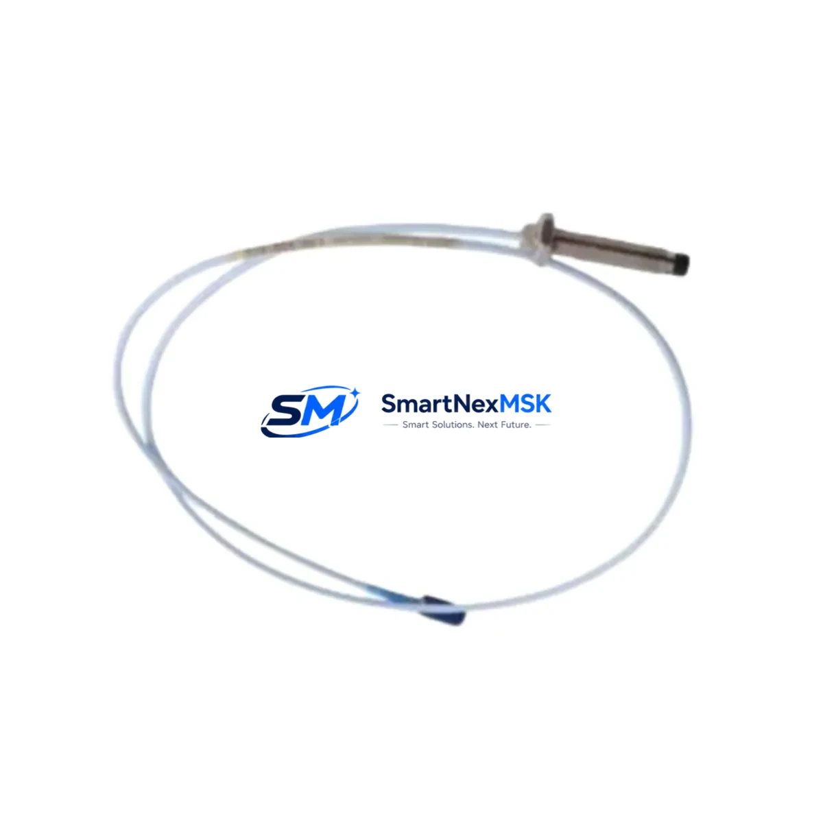
Bently Nevada 330904-00-20-10-02-00 Retrofit-Ready Proximity Probe for 3300 NSv Control Systems
The Bently Nevada 330904-00-20-10-02-00 is an 8mm eddy current proximity probe engineered for the 3300 NSv (Non-contacting Vibration) monitoring platform. As legacy rotating machinery protection systems age and original spare parts become increasingly difficult to source, this probe serves as a verified drop-in replacement for facilities managing turbines, compressors, pumps, and gearboxes that rely on continuous shaft vibration and position monitoring. Whether you are executing a planned outage upgrade, responding to an unplanned probe failure, or modernizing a control cabinet that has been in service for over a decade, the 330904-00-20-10-02-00 is stocked and ready to ship with a 12-month warranty covering manufacturing defects and performance conformance.
Upgrade Compatibility Table
| Parameter | Detail |
|---|---|
| SKU / Part Number | 330904-00-20-10-02-00 |
| Brand | Bently Nevada |
| Series Compatibility | 3300 NSv (Non-contacting Vibration) System |
| Probe Diameter | 8mm |
| Cable Length | 2.0m (integral cable) |
| Extension Cable Compatibility | 3300 XL 8mm Extension Cable (e.g. 330130 series) |
| Driver / Proximitor Compatibility | 3300 XL 8mm Proximitor Sensor (e.g. 330180 series) |
| Installation Interface | M10 x 1.0 thread, standard 3300 NSv bracket mount |
| Communication / Signal | Analog voltage output, compatible with 3500 rack I/O and legacy 3300 monitors |
| Replacement Recommendation | Direct drop-in for 330904-00-20-10-02-00; verify gap voltage at commissioning |
| Commissioning Key Point | Set air gap to achieve –10 VDC ± 0.5 VDC at nominal position |
| Warranty | 12 Months — manufacturing defects and performance conformance |
Retrofit Planning for Existing Automation Systems
Replacing a proximity probe in an operating plant is rarely a standalone task. A successful retrofit of the 330904-00-20-10-02-00 typically involves a coordinated review of the surrounding measurement chain and control architecture. Before scheduling the outage window, maintenance engineers should confirm that the existing 330130-series extension cable is free of insulation damage and connector corrosion, as a degraded cable will introduce noise into the gap voltage signal even with a new probe installed. The Proximitor sensor — commonly a 330180-series module mounted inside the control cabinet — should be inspected for output drift and recalibrated if the previous probe had been operating outside its linear range for an extended period.
For facilities running a Bently Nevada 3500 rack-based monitoring system, the probe signal feeds into 3500/40M or 3500/42M proximity monitor cards. These cards store alarm setpoints and full-scale ranges that must be verified against the replacement probe’s sensitivity specification (typically 7.87 V/mm for 8mm probes) to avoid nuisance trips or missed alarms after the swap. If the plant has migrated part of its monitoring to a System 1 software platform, the channel configuration in System 1 must also be updated to reflect the new probe serial number and calibration data.
In older installations where the 3300 NSv system interfaces with a DCS via a 4–20 mA output conditioner or a Modbus RTU gateway, the signal scaling parameters in the DCS I/O card configuration should be reviewed. A mismatch between the probe’s output range and the DCS input scaling can cause incorrect vibration readings on the operator HMI, leading to false confidence or unnecessary shutdowns. HMI faceplate engineering units and alarm thresholds should be confirmed in the SCADA or DCS configuration tool before returning the machine to service.
Where the retrofit is part of a broader control cabinet upgrade — for example, replacing an aging 3300 rack with a modern 3500/22M transient data interface — the wiring termination at the junction box and the cabinet terminal strip must be mapped carefully. The 330904-00-20-10-02-00 uses a standard coaxial connector at the probe tip and a MIL-spec connector at the extension cable junction; both connection points should be cleaned and torqued to specification during installation. If the cabinet also houses a 3500/20 rack power supply or a 3500/15 power supply module, verify that the supply voltage is within the –24 VDC nominal range required by the Proximitor circuit before energizing the new probe.
For plants that are simultaneously upgrading their PLC platform — for instance, migrating from a legacy Rockwell Automation PLC-5 or Allen-Bradley SLC 500 to a ControlLogix or CompactLogix controller — the vibration monitor’s relay output or analog output wiring to the PLC I/O rack must be re-terminated and the ladder logic or function block program updated to reflect any changes in input card addressing. A programming cable and RSLogix 5000 or Studio 5000 session should be prepared in advance so that program changes can be downloaded and verified during the commissioning window without extending the planned outage.
Downtime Control During System Migration
Minimizing unplanned downtime is the primary concern for any rotating machinery protection upgrade. When replacing the 330904-00-20-10-02-00 on a critical machine train, the recommended approach is to pre-stage all replacement components — probe, extension cable, and Proximitor sensor if required — and perform a bench-level continuity and insulation resistance check before the machine is taken offline. This eliminates the risk of discovering a defective replacement part after the machine has already been shut down.
During the outage, the original probe gap voltage reading should be recorded from the 3500 monitor front panel or System 1 trend display before disconnection. This baseline value allows the commissioning technician to set the new probe to an identical air gap without relying solely on mechanical measurement, reducing the time required to achieve a stable gap voltage within the acceptable window. Once the new probe is installed and the gap voltage is confirmed, the monitor’s bypass or inhibit function should be released and the machine brought back to operating speed under observation, with vibration trend data logged for the first 30 minutes of operation to confirm stable readings.
For facilities with redundant probe configurations (X–Y proximity probe pairs), the second probe in the pair should be inspected and its gap voltage verified during the same outage window, even if it is not being replaced. This avoids a second unplanned outage caused by a probe that was already marginal at the time of the first intervention. All work should be documented in the plant’s maintenance management system with the new probe serial number, installation date, gap voltage as-found and as-left values, and the name of the commissioning technician.
Retrofit Support FAQ
Q1: Is the 330904-00-20-10-02-00 a direct replacement for the original Bently Nevada part?
Yes. This unit is manufactured to the same dimensional and electrical specification as the original 330904-00-20-10-02-00 and is a verified drop-in replacement for 3300 NSv proximity measurement chains. No mechanical modification to the probe mount or extension cable is required.
Q2: What commissioning checks are required after installation?
After mechanical installation, connect the probe to the extension cable and Proximitor sensor, then power the Proximitor and measure the DC gap voltage at the monitor input. Adjust the probe air gap until the voltage reads –10 VDC ± 0.5 VDC at the nominal shaft position. Confirm that the 3500 monitor channel shows a valid OK status and that vibration readings are within expected baseline range before releasing the bypass.
Q3: Can this probe be used with a Bently Nevada 3500 rack system as well as the legacy 3300 system?
Yes. The 330904-00-20-10-02-00 is compatible with both the 3300 NSv Proximitor and the 3500-series proximity monitor cards when paired with the appropriate 330130-series extension cable and 330180-series Proximitor sensor. Confirm the monitor card’s input sensitivity setting matches the 8mm probe specification before commissioning.
Q4: What does the 12-month warranty cover?
The 12-month warranty covers manufacturing defects and performance non-conformance under normal operating conditions. Each unit undergoes pre-shipment functional testing. Warranty claims are supported by SMARTNEXMSK’s technical team; contact sales@smartnexmsk.com with the order number and a description of the observed fault.
© 2026 SMARTNEXMSK. All rights reserved.
Original Source: https://smartnexmsk.com
Contact: sales@smartnexmsk.com | +86 18259474341


