Bently Nevada 330904-00-21-10-01-00 3300 XL NSv Spare: Precision Replacement for Industrial Downtime Control
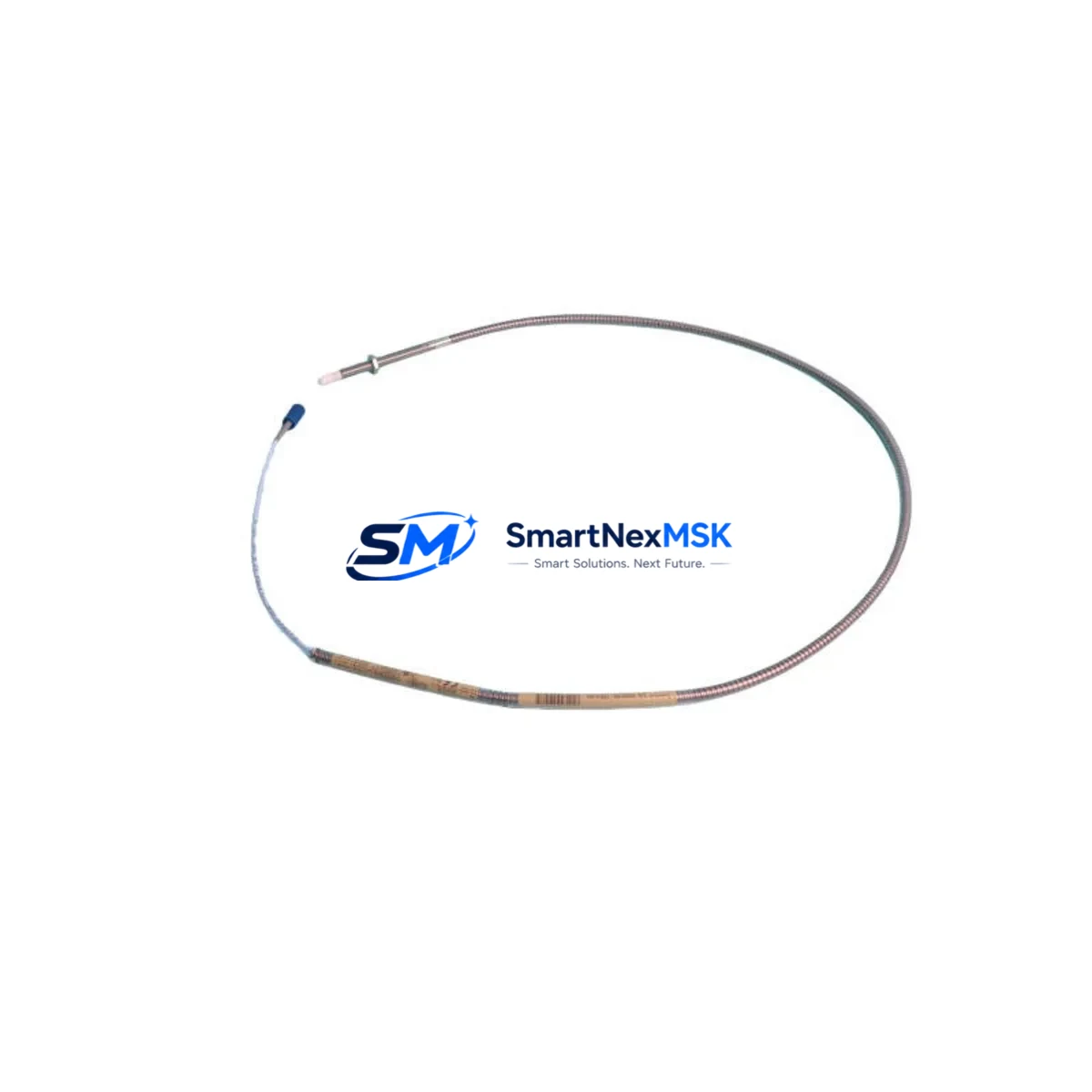
The Bently Nevada 330904-00-21-10-01-00 is an original eddy-current proximity transducer engineered for the 3300 XL NSv series continuous machinery monitoring system. Designed for radial vibration, axial position, and differential expansion measurement on rotating machinery, this transducer is a critical spare for turbines, compressors, pumps, and gearboxes operating in oil & gas, power generation, petrochemical, and heavy industrial environments. Maintaining a verified stock of this part directly reduces unplanned downtime risk and supports rapid fault isolation during machinery health events.
Spare Maintenance Table
| Parameter | Specification |
|---|---|
| Part Number / SKU | 330904-00-21-10-01-00 |
| Brand | Bently Nevada |
| Series | 3300 XL NSv (Non-Standard Voltage) |
| Product Type | Eddy-Current Proximity Transducer |
| Measurement Function | Radial Vibration, Axial Position, Differential Expansion |
| Output Signal | -18 VDC nominal (NSv scale factor) |
| Cable Length | 21 ft (6.4 m) — encoded in SKU suffix -21 |
| Connector Type | 10-32 coaxial, armored extension cable compatible |
| Target Material Compatibility | Steel, 4140/4340 alloy, stainless (verify with calibration) |
| Operating Temperature | -35°C to +177°C (probe tip) |
| Ingress Protection | IP67 (probe body) |
| Compatible Monitor | 3300/16 XL, 3300/20 XL, 3500/42M, 3500/45 |
| Origin | USA (Bently Nevada / Baker Hughes) |
| Condition | Original, New / Surplus New |
| Pre-Shipment Testing | Electrical continuity, impedance, and output linearity verified |
| Warranty | 12 Months from date of shipment |
| Lead Time | In-stock: ships within 1–3 business days |
Maintenance Planning for Continuous Operation
When a 330904-00-21-10-01-00 transducer is flagged for replacement during a planned outage or emergency shutdown, maintenance engineers should treat the event as a trigger for a broader proximity system audit. The 3300 XL NSv loop is a tightly integrated measurement chain — a fault in the transducer rarely exists in isolation.
Begin by inspecting the 330130-080-00-05 extension cable that connects the probe to the proximitor. Extension cables are subject to mechanical fatigue, connector corrosion, and insulation breakdown, particularly in high-vibration or high-temperature zones. A degraded cable will produce erratic gap voltage readings even after a new transducer is installed. Simultaneously, verify the 330180-X1-05 proximitor/driver (or equivalent NSv-rated driver) for correct bias voltage output, typically –18 VDC ±0.5 V at the calibrated gap. A proximitor that has drifted out of specification will cause the new transducer to report false vibration amplitudes.
At the monitor rack level, inspect the 3500/42M Proximitor/Seismic Monitor or 3300/16 XL monitor card for alarm setpoint integrity, OK relay status, and channel-to-channel cross-talk. Confirm that the 3500/20 rack power supply is delivering stable ±24 VDC rails — power supply ripple is a common root cause of baseline noise in proximity channels. If the plant uses a 3500/92 communication gateway or Modbus/OPC-DA interface for DCS integration, verify that channel mapping and scaling factors are consistent with the NSv transducer’s sensitivity.
For installations where the transducer monitors axial thrust position, cross-reference readings against the 330500-02-00 thrust position transducer on the opposing bearing to confirm differential expansion values are within trip margins. In compressor trains, also inspect the 330103-00-08-10-02-00 radial vibration probe on adjacent bearing housings to establish a complete vibration baseline before returning the machine to service.
Terminal blocks, 3500/05 system rack backplane connections, and field junction box wiring should be torqued to specification and inspected for oxidation. Loose terminations in the signal loop introduce impedance discontinuities that mimic transducer faults. Where signal isolation is required between the field loop and the DCS analog input card, confirm that any installed signal isolator or galvanic separator is rated for the –18 VDC NSv signal range and has not drifted. Finally, update the plant’s spare parts register to reflect the replacement and flag a reorder point for the 330904-00-21-10-01-00 to maintain a minimum of one unit on-hand per monitored machine train.
Site Replacement Workflow
Step 1 — Isolation & Permit: Issue a work permit and isolate the monitor channel at the 3500/42M or 3300/16 XL card. Place the channel in bypass to prevent spurious trips during transducer removal.
Step 2 — Gap Measurement: Record the existing installed gap voltage before disconnecting the old 330904-00-21-10-01-00. This baseline confirms whether the fault was in the transducer or elsewhere in the loop.
Step 3 — Transducer Removal: Disconnect the extension cable at the field junction box. Unthread the probe from the bracket using the correct spanner — avoid applying torque to the cable armor. Note the thread engagement depth for reinstallation reference.
Step 4 — New Unit Installation: Install the replacement 330904-00-21-10-01-00 to the same thread depth. Reconnect the 330130 extension cable. Apply anti-seize compound to the probe threads if operating above 120°C.
Step 5 — Gap Setting & Verification: Adjust the probe gap to achieve –10.0 VDC ±0.2 V (or per the machine OEM specification) using a calibrated gap tool. Verify output linearity across the full measurement range using the proximitor’s test points.
Step 6 — Channel Reinstatement: Remove the bypass, confirm OK relay energizes, and verify that vibration and position readings are within expected baseline values. Document the replacement in the plant CMMS with the new unit’s serial number and installation date.
This workflow is compatible with legacy 3300 XL installations and current 3500 series racks, making the 330904-00-21-10-01-00 a direct drop-in replacement that requires no firmware changes or monitor reconfiguration when the NSv driver is already installed.
Spare Parts Support FAQ
Q1: Is the 330904-00-21-10-01-00 compatible with both 3300 XL and 3500 series monitors?
Yes. The 330904-00-21-10-01-00 is designed for the 3300 XL NSv system but is electrically compatible with 3500 series monitors configured for NSv (Non-Standard Voltage) input channels. Always confirm the monitor channel is set to NSv sensitivity (7.87 mV/µm or 200 mV/mil) before installation to avoid scaling errors.
Q2: What pre-shipment checks are performed on each unit?
Every 330904-00-21-10-01-00 shipped from our inventory undergoes electrical continuity verification, coaxial connector impedance check, and output linearity confirmation against a calibrated target. Units that do not meet Bently Nevada factory specifications are quarantined and not offered for sale. A 12-month warranty covers defects in materials and workmanship from the date of shipment.
Q3: How should this transducer be stored as a long-term spare?
Store in the original anti-static packaging in a dry environment between –20°C and +70°C with relative humidity below 85% non-condensing. Inspect connector pins and cable armor annually. For storage exceeding 24 months, perform a bench verification of output voltage before installation. Avoid storing near strong magnetic fields or high-voltage equipment.
Q4: Can you supply multiple units for a fleet-wide spare parts program?
Yes. We support bulk procurement for plant-wide or fleet-wide spare parts strategies. Volume pricing is available for orders of 3 or more units. Lead times for larger quantities are confirmed at order placement. All units in a batch order are sourced from the same verified lot where possible to ensure consistency across your installed base.
© 2026 SMARTNEXMSK. All rights reserved.
Original Source: https://smartnexmsk.com
Contact: sales@smartnexmsk.com | +86 18259474341


