Bently Nevada 330904-00-21-10-02-05/CN Retrofit-Ready Proximity Probe for 3300 NSv Control Systems
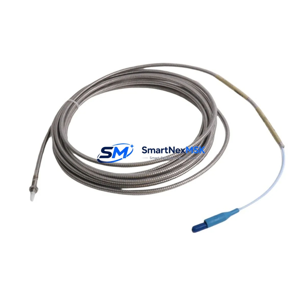
The Bently Nevada 330904-00-21-10-02-05/CN is an eddy-current proximity probe engineered for the 3300 NSv series vibration monitoring platform. As legacy rotating machinery protection systems reach end-of-life or face discontinued spare parts availability, this probe serves as a direct retrofit solution for facilities maintaining turbines, compressors, pumps, and other critical rotating assets. Whether you are replacing a failed sensor, upgrading an aging control cabinet, or migrating from an obsolete monitoring architecture, the 330904-00-21-10-02-05/CN delivers wiring-compatible, drop-in performance with no firmware changes required on the host monitor.
This probe operates within the standard Bently Nevada 3300 NSv eddy-current measurement chain, which includes the proximitor/extension cable assembly and the 3300 XL monitor rack. The 330904-00-21-10-02-05/CN features a 5-metre integral cable, 8 mm tip diameter, and a nominal sensitivity of 7.87 V/mm, consistent with the original factory specification. It is fully interchangeable with earlier 330900 series probes in most installation configurations, making it a preferred choice for brownfield retrofit projects where re-cabling or re-commissioning time must be minimised.
Upgrade Compatibility Table
| Parameter | 330904-00-21-10-02-05/CN | Notes / Retrofit Guidance |
|---|---|---|
| Series Compatibility | Bently Nevada 3300 NSv | Also compatible with 3300 XL 8mm monitor racks |
| Tip Diameter | 8 mm | Verify existing probe boss thread: M10 × 1.0 |
| Cable Length | 5 m integral | Match or replace extension cable (330130 series) accordingly |
| Sensitivity | 7.87 V/mm (200 mV/mil) | Confirm monitor channel scale factor before swap |
| Supply Voltage | −24 VDC nominal | Verify barrier or proximitor output voltage at terminal block |
| Output Range | −2 VDC to −18 VDC | Check gap voltage at installation: target −10 VDC ±0.5 V |
| Communication / Protocol | Analogue (4–20 mA / voltage) | No protocol migration required; analogue signal chain unchanged |
| Connector Type | Integral coaxial (TNC) | Confirm mating connector on extension cable or proximitor input |
| Installation Thread | M10 × 1.0 | Use supplied locknut; torque to 1.1 N·m |
| Replacement Recommendation | Direct drop-in for 330900-00-21-10-02-05 | No re-ranging required if original monitor calibration is intact |
| Commissioning Check | Gap voltage, OK relay, Alert/Danger setpoints | Verify via 3300 XL front-panel display or System 1 software |
| Warranty | 12 Months | Covers manufacturing defects; includes pre-shipment functional test |
Retrofit Planning for Existing Automation Systems
Successful integration of the 330904-00-21-10-02-05/CN into an existing rotating machinery protection system requires a structured pre-installation review. Begin by auditing the current probe installation: confirm the probe boss thread size, the existing gap voltage reading, and the condition of the coaxial extension cable. In many legacy installations, the extension cable — typically a 330130-080-00-00 or equivalent 8-metre assembly — shows insulation degradation or connector corrosion that must be addressed simultaneously with the probe replacement to avoid signal noise or false OK relay trips.
The proximitor module, often a 3300/16 or 3300/55 proximitor mounted in the field junction box or control cabinet, must be verified for output voltage compliance. A worn or out-of-tolerance proximitor will produce incorrect gap voltage even with a new probe installed, leading to erroneous vibration readings. If the proximitor is also at end-of-life, plan to replace it alongside the probe to avoid a second shutdown event.
Within the monitor rack, the 3300 XL 8-channel monitor or the 3500/42M proximity monitor card must have its channel configuration reviewed. Confirm that the scale factor (7.87 V/mm), the OK limits (−2 V to −18 V), and the Alert and Danger setpoints are correctly programmed. If the facility uses Bently Nevada System 1 condition monitoring software, the channel configuration can be verified and backed up before the swap, protecting the existing alarm logic and trend data.
For facilities running a mixed rack with both 3300 NSv probes and 3500 series monitors, note that the 3500/42M accepts the same 8 mm eddy-current probe chain. The 330904-00-21-10-02-05/CN is therefore also applicable in 3500 platform retrofits where the probe and extension cable are being renewed without changing the monitor card. In these cases, confirm the 3500 rack power supply — typically a 3500/15 power supply module — is delivering stable −24 VDC to all probe channels before proceeding.
Control cabinet upgrades often involve replacing the terminal block wiring between the field junction box and the monitor rack. Use shielded twisted-pair cable with the shield grounded at one end only to prevent ground loops. Label all terminals clearly before disconnection, and photograph the existing wiring layout as a reference. If the cabinet also houses a 3300 RAM (Rack Adapter Module) or a 3300 TDI (Transient Data Interface), ensure these modules are powered down in the correct sequence per the Bently Nevada rack shutdown procedure to avoid data loss.
Where the retrofit scope includes I/O expansion — for example, adding shaft absolute vibration channels using a combination of the 330904 proximity probe and a seismic velocity sensor — coordinate the channel mapping with the DCS or safety system integrator. The analogue output from the 3300 XL monitor feeds directly into the DCS I/O card; confirm the signal range (4–20 mA or 0–10 V) matches the DCS input card specification before commissioning.
Downtime Control During System Migration
Minimising unplanned downtime during a proximity probe replacement is achievable with disciplined pre-work. Before the maintenance window opens, stage all replacement components — the 330904-00-21-10-02-05/CN probe, the extension cable, locknut, and any required proximitor — at the work site. Pre-test the new probe and proximitor assembly on a bench using a portable calibration target to confirm gap voltage and sensitivity before installation. This eliminates the risk of discovering a defective component after the machine is already shut down.
During the replacement, use the existing probe boss as a reference for gap setting. Insert the new 330904-00-21-10-02-05/CN and adjust the gap to achieve −10 VDC ±0.5 V at the proximitor output terminal. Record the as-found and as-left gap voltage values in the maintenance log. Once the probe is secured with the locknut, reconnect the extension cable and verify the OK relay status on the 3300 XL monitor front panel before restarting the machine.
If the facility operates a redundant monitoring configuration — for example, an XY probe pair on a journal bearing — replace one probe at a time while the machine remains in a safe, monitored state on the remaining channel. This approach preserves continuous vibration monitoring throughout the maintenance activity and avoids a full bypass of the protection system. After both probes are replaced and verified, perform a slow-roll check to confirm that the vibration baseline is consistent with historical trend data in System 1 before returning the machine to full load.
For facilities with tight maintenance windows, pre-configure the replacement channel in System 1 offline and use the configuration download function to push the verified settings to the monitor rack immediately after the probe swap. This eliminates manual re-entry of setpoints and reduces the risk of configuration errors under time pressure.
Retrofit Support FAQ
Q1: Is the 330904-00-21-10-02-05/CN a direct replacement for the 330900-00-21-10-02-05?
Yes. The 330904 series supersedes the 330900 series in most 3300 NSv and 3300 XL installations. The physical dimensions, thread size, cable length, and sensitivity specification are identical. No re-ranging or recalibration of the monitor channel is required provided the original calibration data is intact. Confirm the gap voltage after installation as a final verification step.
Q2: What wiring checks are required before installing the new probe?
Inspect the coaxial extension cable for insulation damage, connector corrosion, and continuity. Verify that the proximitor output voltage is within the −2 V to −18 V OK range with the cable disconnected from the old probe. Check the terminal block connections in the control cabinet for tightness and correct labelling. Ensure the shield drain wire is grounded at the monitor rack end only to prevent ground loops that can introduce noise into the vibration signal.
Q3: How do I verify compatibility with my existing 3500 series monitor rack?
The 330904-00-21-10-02-05/CN is compatible with the 3500/42M proximity monitor card when used with the standard 3300 NSv probe chain. Confirm the channel configuration in the 3500 Rack Configuration Software (RCS) matches the probe sensitivity (7.87 V/mm) and OK limits. If the rack uses a 3500/20 or 3500/22M power supply, verify that the −24 VDC probe power rail is within specification before connecting the new probe.
Q4: What does the 12-month warranty cover, and is pre-shipment testing performed?
Every 330904-00-21-10-02-05/CN unit supplied by SMARTNEXMSK undergoes a pre-shipment functional test that verifies sensitivity, OK voltage range, and cable integrity against the Bently Nevada factory specification. The 12-month warranty covers manufacturing defects in materials and workmanship from the date of shipment. It does not cover damage resulting from incorrect installation, over-torquing of the locknut, or exposure to environments outside the rated temperature and chemical resistance limits. Warranty claims are processed within 5 business days of receipt of the returned unit.
—
© 2026 SMARTNEXMSK. All rights reserved.
Original Source: https://smartnexmsk.com
Contact: sales@smartnexmsk.com | +86 18259474341


