Bently Nevada 330904-00-23-05-01-00 Retrofit-Ready Proximity Transducer for 3300 XL NSv Control Systems
The Bently Nevada 330904-00-23-05-01-00 is a high-precision eddy-current proximity transducer engineered for the 3300 XL NSv vibration monitoring platform. As legacy 3300 Series installations approach end-of-support milestones, plant engineers and reliability teams are increasingly sourcing verified retrofit-ready replacements that preserve existing wiring infrastructure, rack geometry, and software configuration without requiring a full system overhaul. This unit delivers exactly that: a mechanically and electrically compatible drop-in solution for facilities committed to extending the operational life of their Bently Nevada 3300 XL NSv architecture.
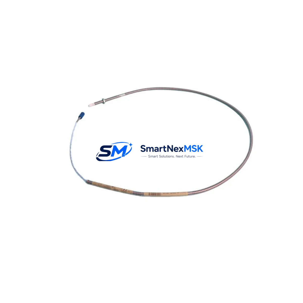
The 330904-00-23-05-01-00 is a 5-metre cable assembly variant within the 330900 Series proximity transducer family, designed to interface directly with the 3300 XL NSv proximitor/seismic monitor. Its 8 mm tip diameter, standard Bently Nevada connector pinout, and -24 VDC bias voltage specification ensure seamless integration with existing field wiring and junction boxes. Engineers replacing worn or failed transducers in rotating machinery applications — including steam turbines, gas compressors, centrifugal pumps, and gearboxes — can install this unit without modifying the 3500/3300 rack wiring or reconfiguring the System 1 software database.
Upgrade Compatibility Table
| Parameter | 330904-00-23-05-01-00 (This Unit) | Retrofit Notes |
|---|---|---|
| Compatible Platform | Bently Nevada 3300 XL NSv | Direct replacement; no rack modification required |
| Tip Diameter | 8 mm | Matches standard 3300 Series probe bore; verify probe holder ID |
| Cable Length | 5 m (extension cable compatible) | Use 330130 extension cable for longer runs; total system length ≤ 9 m |
| Bias Voltage | -24 VDC nominal | Confirm proximitor output range matches monitor card input spec |
| Connector Type | Standard Bently Nevada coaxial | Compatible with existing field junction boxes and armoured conduit |
| Communication / Protocol | Analogue (4–20 mA / voltage output via proximitor) | No protocol migration required; signal chain unchanged |
| Installation Interface | 3300 XL NSv Proximitor/Seismic Monitor | Verify monitor firmware version supports NSv transducer family |
| Replacement for | 330900-00-23-05-01-00 and equivalent legacy part numbers | Cross-reference OEM documentation before installation |
| Commissioning Requirement | Gap voltage verification at -10.0 VDC ± 0.5 VDC | Use Bently Nevada gap tool or calibrated multimeter at terminal block |
| Warranty | 12 Months | Covers manufacturing defects; includes pre-shipment functional test |
Retrofit Planning for Existing Automation Systems
A successful retrofit of the 330904-00-23-05-01-00 begins well before the maintenance window opens. The first step is a full audit of the existing 3300 XL NSv rack assembly. Technicians should document the slot assignments of each 3300 XL NSv Proximitor/Seismic Monitor card, confirm the rack’s power supply module output capacity — typically a 3300 XL Power Supply rated at 5 A — and verify that the backplane connectors show no signs of corrosion or mechanical damage. If the rack houses additional I/O modules such as the 3300 XL 16-Channel I/O Module, their wiring schedules must be preserved and clearly labelled before any transducer work begins.
Field wiring is the most time-sensitive element of any proximity transducer replacement. The 330904-00-23-05-01-00 uses the same coaxial cable and connector standard as the broader 330900 Series, so existing armoured conduit runs and junction box terminations can typically be reused. Where cable runs exceed 5 metres, a 330130 Extension Cable is required to bridge the transducer to the proximitor input. Engineers should also inspect the 3300 XL NSv Proximitor/Seismic Monitor’s terminal block for correct torque on all screw terminals, as loose connections are a leading cause of spurious vibration alarms during post-replacement commissioning.
For facilities running System 1 Evolution or System 1 Classic software, the transducer database entry must be verified against the new part number. In most cases, the 330904-00-23-05-01-00 maps directly to the existing transducer type definition, and no software changes are required. However, if the plant’s DCS — such as a Honeywell Experion PKS or an Emerson DeltaV system — receives vibration data via a 3500/22M Transient Data Interface or a 3500/92 Communication Gateway Module, the data mapping tables should be reviewed to confirm that channel assignments and engineering unit scaling remain intact after the swap.
HMI screens connected to the vibration monitoring network — whether running on a dedicated Bently Nevada operator workstation or integrated into a broader SCADA display — should be tested in simulation mode before the transducer is energised. Confirm that the gap voltage, direct vibration, and 1X/2X vector displays update correctly and that no latent alarms are triggered by the new transducer’s initial output. If the plant uses a 3500/42M Proximitor/Seismic Monitor in parallel with the 3300 XL NSv rack for redundancy, both channels must be verified independently before returning the machine to service.
Downtime Control During System Migration
Minimising unplanned downtime during a proximity transducer replacement requires a structured pre-outage preparation protocol. Before the maintenance window, the engineering team should export the full System 1 configuration database and store a timestamped backup on an isolated network drive. All active alarm setpoints — including danger, alert, and relay output thresholds configured in the 3300 XL NSv monitor — should be documented in a commissioning checklist so they can be verified against live readings immediately after the new 330904-00-23-05-01-00 is installed and gapped.
During the replacement, the affected machine train should be isolated at the control system level by placing the relevant monitor channels into bypass mode. This prevents spurious trip signals from propagating to the emergency shutdown system or the plant DCS while the transducer is disconnected. Once the new transducer is installed and the gap voltage is confirmed at -10.0 VDC ± 0.5 VDC using a calibrated multimeter at the proximitor terminal block, the bypass can be lifted and the channel returned to normal monitoring. The entire swap — from isolation to re-energisation — can typically be completed within a two-hour planned outage window when all materials and documentation are staged in advance.
To further protect original program logic, no changes should be made to the 3300 XL NSv monitor’s internal configuration during the transducer replacement. If firmware updates are planned for the monitor card or the 3500/92 Communication Gateway Module, these should be scheduled as a separate maintenance activity to avoid compounding variables during commissioning. Keeping the transducer replacement scope tightly defined is the single most effective strategy for maintaining field control continuity and meeting the plant’s reliability targets.
Retrofit Support FAQ
Q1: Is the 330904-00-23-05-01-00 a direct replacement for the 330900-00-23-05-01-00?
In most installations, yes. Both units share the same 8 mm tip diameter, coaxial connector standard, and -24 VDC bias voltage specification. The primary difference is the cable assembly revision. We recommend cross-referencing the OEM part number against your existing proximitor documentation before installation to confirm compatibility with your specific 3300 XL NSv monitor firmware version.
Q2: What commissioning checks are required after installation?
After mechanical installation, verify the gap voltage at the proximitor terminal block using a calibrated multimeter. The target reading is -10.0 VDC ± 0.5 VDC with the probe tip positioned at the manufacturer-specified gap distance from the shaft. Confirm that the System 1 software displays a valid direct vibration reading and that no alert or danger alarms are active before lifting the channel bypass.
Q3: Can I reuse the existing field wiring and junction box terminations?
Yes, in the vast majority of cases. The 330904-00-23-05-01-00 uses the standard Bently Nevada coaxial connector, which is compatible with existing armoured conduit runs and junction box wiring. If the cable run exceeds 5 metres, a 330130 Extension Cable must be used. Inspect all terminal block connections for correct torque and signs of corrosion before re-energising the circuit.
Q4: What does the 12-month warranty cover, and is pre-shipment testing performed?
Every 330904-00-23-05-01-00 unit undergoes a functional pre-shipment test to verify electrical continuity, bias voltage output, and connector integrity before dispatch. The 12-month warranty covers manufacturing defects in materials and workmanship from the date of shipment. Warranty claims are supported by our technical team at sales@smartnexmsk.com, and replacement units are dispatched within 3 business days of a confirmed defect report.
© 2026 SMARTNEXMSK. All rights reserved.
Original Source: https://smartnexmsk.com
Contact: sales@smartnexmsk.com | +86 18259474341


