Bently Nevada 330905-00-02-05-02-00 Maintenance-Ready Spare for 3300 XL Automation
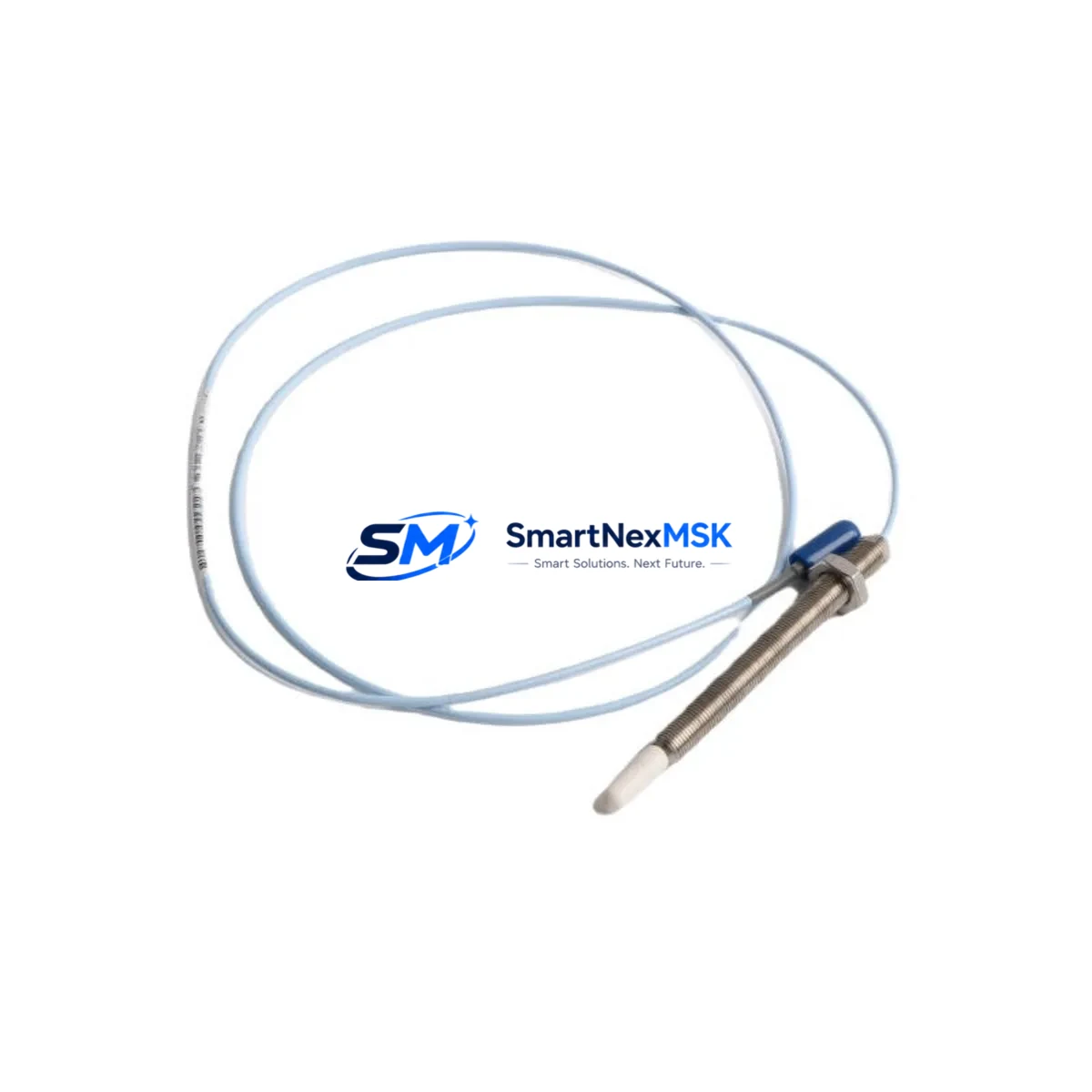
The Bently Nevada 330905-00-02-05-02-00 is an original 8mm proximity transducer engineered for the 3300 XL continuous vibration monitoring system. In rotating machinery environments — turbines, compressors, pumps, and gearboxes — this transducer serves as the primary sensing element for shaft radial vibration, axial position, and eccentricity measurement. When this component fails or degrades, the entire vibration protection loop is compromised, placing critical rotating assets at risk of undetected mechanical fault progression and unplanned shutdown.
For maintenance engineers managing condition monitoring infrastructure, stocking a verified replacement of the 330905-00-02-05-02-00 is a fundamental element of any predictive maintenance (PdM) or reliability-centered maintenance (RCM) program. This transducer is supplied as an original spare, fully tested prior to shipment, and backed by a 12-month warranty covering manufacturing defects and performance conformance to Bently Nevada 3300 XL system specifications.
Spare Maintenance Table
| Parameter | Specification |
|---|---|
| Part Number | 330905-00-02-05-02-00 |
| Brand | Bently Nevada (Baker Hughes) |
| Series | 3300 XL |
| Transducer Type | 8mm Proximity Transducer (Eddy Current) |
| Measurement Function | Radial Vibration, Axial Position, Eccentricity |
| Output Signal | -18 VDC nominal (with matched driver/extension cable) |
| Sensitivity | 7.87 V/mm (200 mV/mil) |
| Linear Range | 0.25 mm to 2.25 mm (10 to 90 mil) |
| Operating Temperature | -35°C to +121°C |
| Target Material Compatibility | AISI 4140 steel (standard); other alloys per calibration |
| Connector | Integral coaxial, compatible with 3300 XL extension cables |
| Installation Environment | Industrial: turbine halls, compressor stations, pump skids |
| Compatibility | 3300 XL Monitor System, 3500 Series (with adapter), TK3 Driver |
| Origin | USA |
| Warranty | 12 Months — tested before shipment |
Maintenance Planning for Continuous Operation
When a 330905-00-02-05-02-00 proximity transducer is flagged for replacement during a scheduled outage or emergency shutdown, experienced maintenance engineers know that the transducer itself is rarely the only component requiring attention. A thorough inspection of the complete vibration measurement loop is essential to restore system integrity and avoid repeat failures.
Begin with the 3300 XL extension cable (typically 5-metre or 9-metre armored coaxial) that connects the transducer to the driver. Extension cables are subject to mechanical fatigue, connector corrosion, and insulation breakdown in high-temperature or high-vibration zones — replace the cable whenever the transducer is changed to eliminate a latent fault source. Next, inspect the 3300 XL proximitor/driver module (such as the 330180 or 330130 series) mounted in the monitor rack; a degraded driver will produce erratic gap voltage even with a new transducer installed.
Inside the monitor rack, verify the 3500/40M or 3300/16 vibration monitor card for alarm setpoint integrity and channel calibration. If the system uses a 3500/22M transient data interface or a 3500/42M proximitor I/O module, confirm that the channel configuration matches the new transducer’s sensitivity and gap voltage range. For plants running a System 1 Evolution condition monitoring platform, update the transducer configuration in the software database to reflect the replacement.
On the power supply side, check the 3500 rack power supply module (typically 88-132 VAC or 18-32 VDC input) for output voltage stability; a sagging supply rail will cause false vibration readings across all channels. If the control cabinet houses a Bently Nevada 3300/55 keyphasor module, inspect the keyphasor transducer and its gap setting simultaneously — keyphasor signal integrity is critical for phase-referenced vibration analysis and balancing operations.
For plants with older 3300 Series (non-XL) infrastructure, the 330905-00-02-05-02-00 can serve as a direct upgrade path when paired with the appropriate 3300 XL driver, extending system life without full rack replacement. Document all gap voltage readings (typically -10.0 VDC ±0.5 VDC at the nominal air gap) before and after installation to confirm correct transducer-to-target alignment and establish a new baseline for trend monitoring.
Site Replacement Workflow
Step 1 — Pre-replacement verification: Confirm the replacement 330905-00-02-05-02-00 matches the installed transducer’s thread size (M10 x 1), cable length, and connector type. Cross-reference the existing calibration record for target material and gap voltage baseline.
Step 2 — Safe isolation: Coordinate with the control room to inhibit the vibration channel alarm and trip outputs before disconnecting the transducer. Record the current gap voltage and vibration amplitude for post-installation comparison.
Step 3 — Physical replacement: Remove the old transducer using the correct spanner, noting the locknut position and thread engagement depth. Install the new 330905-00-02-05-02-00, set the air gap to the specified nominal value (typically 1.0 mm / 40 mil for standard steel targets), and secure the locknut. Reconnect the extension cable and verify connector seating.
Step 4 — Functional verification: With the channel still inhibited, power the driver and measure gap voltage at the monitor rack. Confirm the reading falls within the linear range specification. Sweep the transducer through its linear range if possible to verify output linearity.
Step 5 — Return to service: Remove the channel inhibit, confirm alarm and trip setpoints are active, and log the replacement in the maintenance management system (CMMS) with the new baseline gap voltage. Update the spare parts inventory to trigger reorder of a replacement unit.
This workflow minimizes downtime, ensures system compatibility, and maintains the integrity of the vibration protection loop — critical for assets where an undetected mechanical fault can escalate to catastrophic failure within minutes.
Spare Parts Support FAQ
Q: Is the 330905-00-02-05-02-00 compatible with both 3300 XL and older 3300 Series monitor racks?
A: The 330905-00-02-05-02-00 is designed for the 3300 XL system. Compatibility with legacy 3300 Series racks depends on the driver module version. We recommend confirming the driver part number before installation. Our technical team can assist with compatibility verification prior to shipment.
Q: How is each unit tested before shipment?
A: Every 330905-00-02-05-02-00 unit undergoes electrical continuity, insulation resistance, and gap voltage output verification against Bently Nevada factory specifications before dispatch. A test report is available upon request. The 12-month warranty covers performance conformance from the date of shipment.
Q: What is the recommended spare parts stocking strategy for this transducer?
A: For plants with 4 or more 3300 XL measurement points, we recommend maintaining a minimum of 2 units on-site. Given typical MTBF data for proximity transducers in high-temperature or high-vibration environments, a 12–18 month replenishment cycle is standard practice. Pairing on-site stock with a confirmed supplier relationship ensures rapid emergency fulfillment.
Q: Can this transducer be used to replace a competitor’s 8mm eddy current probe in the same installation?
A: Direct cross-brand substitution is not recommended without full system recalibration, as sensitivity coefficients and gap voltage ranges differ between manufacturers. The 330905-00-02-05-02-00 is optimized for use within the Bently Nevada 3300 XL signal chain. Contact our engineering support team for cross-reference guidance specific to your installation.
© 2026 SMARTNEXMSK. All rights reserved.
Original Source: https://smartnexmsk.com
Contact: sales@smartnexmsk.com | +86 18259474341


