Bently Nevada 330905-00-05-05-01-00 Retrofit-Ready Proximity Transducer for 3300 XL Control Systems
The Bently Nevada 330905-00-05-05-01-00 is a high-precision proximity transducer designed for the 3300 XL NSv (Non-contact Shaft Vibration) monitoring platform. As legacy vibration monitoring systems reach end-of-life or face discontinued spare part availability, this unit serves as a verified retrofit-ready replacement for aging 3300 Series installations across turbines, compressors, pumps, and rotating machinery in oil & gas, power generation, and heavy industrial environments.
SMARTNEXMSK maintains in-stock inventory of the 330905-00-05-05-01-00 with pre-shipment functional testing, full traceability documentation, and a 12-month warranty — enabling procurement teams and reliability engineers to execute planned or emergency replacements with confidence and minimal lead time.
Upgrade Compatibility Table
| Parameter | Detail |
|---|---|
| SKU / Part Number | 330905-00-05-05-01-00 |
| Compatible Platform | Bently Nevada 3300 XL NSv Series |
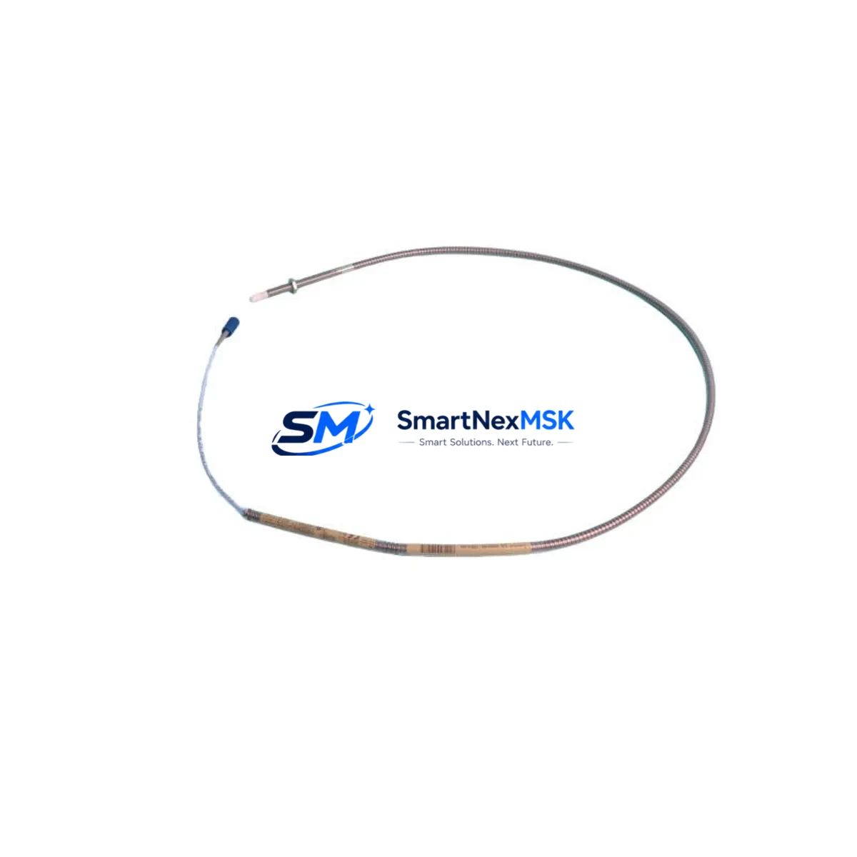
| Transducer Type | Eddy-Current Proximity Transducer |
| Cable Length | 5 m (extension cable) |
| Gap Voltage Range | -10 VDC nominal (standard Bently Nevada gap) |
| Connector Interface | Standard BNC / coaxial, compatible with 3300 XL monitor inputs |
| Mounting Thread | M8 standard probe tip thread |
| Installation Requirement | Verify probe-to-shaft gap (typically 1.0–2.5 mm); recalibrate after installation |
| Communication Compatibility | Analog 4–20 mA / voltage output; compatible with 3300 XL monitor cards |
| Replacement Recommendation | Direct drop-in for 330905 series; verify extension cable and driver pairing |
| Commissioning Focus | Gap setting, signal polarity, OK relay verification, alarm setpoint confirmation |
| Warranty | 12 Months — covers manufacturing defects and functional failure under normal use |
Retrofit Planning for Existing Automation Systems
Replacing a proximity transducer in an operating plant requires careful pre-engineering to avoid unplanned downtime and signal integrity issues. The 330905-00-05-05-01-00 is engineered to integrate directly into existing 3300 XL NSv monitor racks without requiring rack replacement or rewiring of the junction box terminal blocks.
Before initiating the swap, engineers should confirm the paired Bently Nevada 330130 extension cable length and condition, as cable impedance directly affects the system’s gap voltage calibration. The Bently Nevada 330180 driver (or equivalent proximitor) must also be verified for compatibility with the 330905 probe body — mismatched driver-probe combinations are a common source of commissioning errors during retrofit projects.
For installations where the Bently Nevada 3300/16 monitor card or 3300/20 dual-channel monitor is still in service, the 330905-00-05-05-01-00 maintains full electrical compatibility. If the site is migrating from an older 3300 Series rack to a newer System 1 or 3500 Series platform, the transducer itself remains reusable — only the monitor card and I/O termination module require updating.
Terminal wiring at the field junction box should be documented before removal. The coaxial signal cable shield grounding practice must be preserved to prevent ground loop interference, particularly in high-EMI environments near variable frequency drives or large motor starters. When the control cabinet also houses a Bently Nevada 3300/55 power supply module, verify that the supply rail voltage is within specification before energizing the new transducer.
For plants running Bently Nevada TDXnet or System 1 Evolution software, the channel configuration — including probe type, scale factor, and alarm setpoints — must be re-entered or imported from a saved configuration backup after the hardware swap. HMI screens tied to vibration trend displays should be validated to confirm the new channel is reporting correctly before returning the machine to service.
Sites performing I/O expansion as part of a broader control system upgrade may also be installing additional Bently Nevada 3500/42M velocity and acceleration monitor modules alongside the proximity transducer replacement. In these cases, rack slot assignments and module addressing must be planned in advance to avoid conflicts with existing channel maps.
Downtime Control During System Migration
Minimizing production interruption during a proximity transducer replacement requires a structured hot-swap or planned outage protocol. For critical rotating machinery, the preferred approach is to schedule the replacement during a planned maintenance window, pre-stage the 330905-00-05-05-01-00 with gap-setting tools and a calibrated reference target, and have a technician verify the OK relay status immediately after installation before releasing the machine to operations.
Where the control system supports channel bypass or maintenance override — such as in Bently Nevada 3500 Series racks with software-configurable bypass — the affected channel can be placed in bypass mode to prevent spurious shutdowns during the physical swap. This preserves the original program logic and alarm architecture while the transducer is being replaced and re-gapped.
For legacy 3300 XL racks without bypass capability, coordinating with the DCS or safety system operator to temporarily mask the vibration trip signal is essential. The Bently Nevada 3300/25 keyphasor module, if present, should remain powered throughout the swap to maintain phase reference continuity for other channels on the same shaft.
Post-installation, a functional acceptance test should confirm: gap voltage within the –10 VDC ±0.5 V window, OK relay energized, vibration reading within baseline ±10%, and no alarm or danger relay activation at normal operating speed. All test results should be recorded in the site’s maintenance management system before the work order is closed. SMARTNEXMSK provides pre-shipment test reports for each 330905-00-05-05-01-00 unit to support site acceptance documentation.
Retrofit Support FAQ
Q1: Is the 330905-00-05-05-01-00 a direct replacement for all 330905 suffix variants?
The 330905-00-05-05-01-00 is the specific configuration with a 5 m armored extension cable and standard connector. Other suffix variants differ in cable length or connector type. Confirm your existing cable length and connector style before ordering. SMARTNEXMSK can cross-reference your existing part number to confirm compatibility.
Q2: What commissioning steps are required after installation?
After physical installation, set the probe-to-shaft gap to the manufacturer-specified range (typically 1.0–2.5 mm, verified with a gap voltage meter). Confirm the OK relay is energized, check the vibration reading against baseline, and validate alarm and danger setpoints in the monitor card. For System 1 or TDXnet-connected installations, re-verify the channel configuration in software.
Q3: How do I verify wiring compatibility with my existing terminal block layout?
The 330905-00-05-05-01-00 uses the standard Bently Nevada coaxial signal path (center conductor = signal, shield = common). Terminal block connections at the junction box follow the same pinout as all 330905 series probes. Refer to Bently Nevada installation drawing 141536-01 or contact SMARTNEXMSK for wiring documentation support.
Q4: What does the 12-month warranty cover?
The 12-month warranty covers manufacturing defects, functional failure under normal operating conditions, and out-of-specification gap voltage output. It does not cover physical damage from improper installation, over-torquing of the probe tip, or exposure to fluids outside the rated specification. Each unit ships with a pre-shipment functional test report. Warranty claims are processed directly through SMARTNEXMSK with a target response time of 2 business days.
© 2026 SMARTNEXMSK. All rights reserved.
Original Source: https://smartnexmsk.com
Contact: sales@smartnexmsk.com | +86 18259474341


