Bently Nevada 330905-00-08-05-02-00 Retrofit-Ready Proximity Transducer for 3300 XL Control Systems
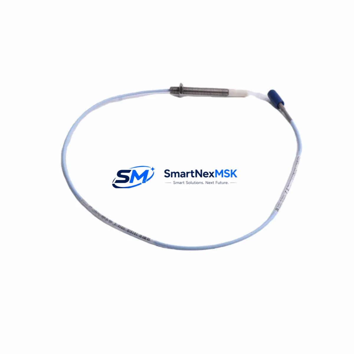
The Bently Nevada 330905-00-08-05-02-00 is an 8mm eddy-current proximity transducer engineered for the 3300 XL Series vibration monitoring platform. As legacy machinery protection systems reach end-of-life or face discontinued spare-parts availability, this transducer serves as a verified drop-in replacement for aging 3300 Series and early 3300 XL installations. Whether you are executing a planned control-cabinet upgrade, recovering from an unplanned shutdown, or migrating a turbine protection loop to a modern monitoring architecture, the 330905-00-08-05-02-00 delivers the dimensional accuracy, output linearity, and signal integrity required to maintain continuous machinery protection without rewriting existing vibration alarm setpoints.
Procurement teams and reliability engineers sourcing this transducer typically encounter it in rotating-machinery applications including steam turbines, gas compressors, centrifugal pumps, and large induction motors where radial shaft vibration, axial position, and differential expansion measurements are critical. The 8mm tip diameter and standard 5-metre integral cable make it directly interchangeable with earlier 330905 variants, eliminating the need for conduit rework or junction-box modifications during a like-for-like swap.
Upgrade Compatibility Table
| Parameter | 330905-00-08-05-02-00 (This Unit) | Retrofit Notes |
|---|---|---|
| Tip Diameter | 8 mm | Matches standard 3300 XL probe bore; no bracket modification required |
| Cable Length | 5 m (integral) | Verify total loop length with extension cable 330130-045-00-CN; max 9 m system |
| Output Signal | −200 mV/mil (−7.87 V/mm) | Compatible with 3300 XL monitor input cards; no gain rescaling needed |
| Supply Voltage | −24 VDC (nominal) | Confirm power supply 3300/20 or equivalent delivers ≥ 18 VDC under load |
| Connector Type | Standard BNC / coaxial | Mates directly with 3300 XL proximitor/extension cable connectors |
| Monitor Compatibility | 3300 XL, 3300/16, 3300/20, 3500 Series (with adapter) | For 3500 Series migration, verify channel configuration in System 1 software |
| Installation Standard | API 670 compliant | Suitable for machinery protection per API 670 4th and 5th edition |
| Replacement Scope | Direct replacement for 330905-00-08-05-00-00 and -01-00 variants | Confirm suffix digits match target gap voltage and cable configuration |
| Warranty | 12 Months | Covers manufacturing defects; includes pre-shipment functional test report |
Retrofit Planning for Existing Automation Systems
A successful retrofit of the 330905-00-08-05-02-00 into an operating machinery protection loop requires systematic verification across several interdependent subsystems. Begin with the proximitor: the companion Bently Nevada 330180-91-05 proximitor (or equivalent 3300 XL proximitor module) must be confirmed serviceable, as a degraded proximitor will produce erratic gap voltage even with a new transducer installed. Check the proximitor’s bias voltage output at the OK terminal before condemning the transducer.
Next, audit the extension cable. Many field installations use the Bently Nevada 330130-045-00-CN 4.5-metre extension cable to bridge the distance between the probe tip and the proximitor mounted on the control cabinet. Inspect the coaxial connector for corrosion, verify the cable shield continuity, and confirm the total system cable length does not exceed the 9-metre maximum for the 8mm system. Exceeding this limit shifts the linear range and invalidates calibrated gap-voltage alarm setpoints stored in the 3300 XL monitor card.
At the monitor level, the 3300/16 dual-channel vibration monitor or the 3300/20 power supply module feeding the transducer loop should be inspected for capacitor aging and relay contact wear. If the site is simultaneously upgrading from a 3300 XL rack to a 3500 Series rack, the I/O terminal block wiring must be remapped: the 3500/42M four-channel monitor uses a different terminal assignment than the legacy 3300 card, and the System 1 configuration database must be updated to reflect the new channel addresses before the loop is re-energised.
For sites running a DCS integration—such as a Honeywell Experion PKS or Emerson DeltaV system receiving 4–20 mA vibration retransmission signals from the 3300 XL rack—verify that the retransmission scaling in the monitor card matches the DCS analogue input range. A transducer swap does not alter the monitor’s retransmission output, but a simultaneous monitor card replacement may reset scaling parameters to factory defaults, causing DCS high-vibration alarms to trigger at incorrect engineering-unit values.
HMI screens on operator workstations displaying shaft vibration trends should be reviewed after the retrofit. If the site uses a GE iFIX, Wonderware InTouch, or Ignition SCADA platform, confirm that the tag addresses and alarm limits displayed on the rotating-equipment overview screen still correspond to the correct monitor channel after any rack or card renumbering. A mismatch between the physical channel and the HMI tag is a common post-retrofit commissioning error that can mask a genuine vibration alarm.
Finally, document the as-found and as-left gap voltage readings. The 330905-00-08-05-02-00 has a nominal linear range of −10 VDC to −18 VDC, with the target operating gap typically set to produce −10.5 VDC ± 0.5 VDC at the proximitor output. Record these values in the site’s maintenance management system alongside the transducer serial number and installation date to support future predictive-maintenance trending and warranty claims.
Downtime Control During System Migration
Minimising unplanned downtime during a proximity transducer replacement requires pre-staging all replacement components before the maintenance window opens. Confirm that the 330905-00-08-05-02-00 unit, the companion proximitor, and any required extension cable are on-site and have passed incoming inspection before scheduling the outage. A pre-shipment functional test report accompanies each unit shipped by SMARTNEXMSK, providing gap-voltage linearity data that can be compared against the site’s acceptance criteria without requiring a full bench calibration on arrival.
During the swap, use the 3300 XL monitor’s bypass function to place the affected channel in maintenance bypass before disconnecting the transducer. This prevents a spurious OK-relay dropout from triggering a turbine trip or compressor shutdown while the loop is open. Restore the bypass only after the new transducer is installed, the gap voltage is verified within the linear range, and the OK indicator on the monitor card is confirmed green.
If the site cannot tolerate even a brief bypass period, consider a hot-standby approach using a spare 3300 XL monitor card pre-configured with identical setpoints. Swap the card while the machine remains online, transfer the transducer connection, and verify the gap voltage before removing the bypass. This technique is particularly effective in continuous-process plants where a single compressor or pump supports an entire production train and a cold shutdown carries significant economic consequence.
Preserve the original program logic in the safety PLC or DCS by exporting a backup of the current configuration before any hardware changes. For sites using a Rockwell Automation ControlLogix or Siemens S7-400 safety controller receiving discrete trip signals from the 3300 XL rack, ensure the safety program version is archived and the controller is in Run mode with the trip output inhibited during the maintenance window. Restore normal operation only after all vibration channels have been verified and the maintenance bypass has been removed.
Retrofit Support FAQ
Q1: Is the 330905-00-08-05-02-00 a direct replacement for the 330905-00-08-05-00-00?
Yes. The suffix digits -02-00 indicate a 5-metre integral cable with a standard coaxial connector, which is dimensionally and electrically identical to the -00-00 and -01-00 variants for the purposes of 3300 XL system compatibility. Verify the total system cable length and confirm the proximitor model before installation. No setpoint changes are required for a like-for-like swap.
Q2: What commissioning checks are required after installation?
After mechanical installation, measure the gap voltage at the proximitor OK terminal with the shaft stationary at the target air gap. The reading should fall within −10.5 VDC ± 0.5 VDC for a standard 8mm system. Confirm the OK indicator is green, check that the vibration reading on the monitor card is within the expected baseline range, and verify that the DCS or SCADA system is receiving a valid retransmission signal. Document as-left gap voltage and transducer serial number in the site CMMS.
Q3: How do I verify wiring compatibility with my existing 3300 XL rack?
The 330905-00-08-05-02-00 uses a standard coaxial signal path: the centre conductor carries the −24 VDC supply and the modulated output signal, while the shield is the signal return. This is identical to all 3300 Series and 3300 XL transducers. Connect the integral cable to the existing extension cable or directly to the proximitor input using the existing coaxial connector. No rewiring of the monitor card terminal block is required for a like-for-like replacement.
Q4: What does the 12-month warranty cover, and what documentation is provided?
The 12-month warranty covers manufacturing defects in materials and workmanship from the date of shipment. Each unit is shipped with a pre-shipment functional test report confirming gap-voltage linearity across the full operating range. In the event of a warranty claim, contact SMARTNEXMSK with the transducer serial number and the test report reference. Warranty does not cover damage resulting from incorrect installation, over-range mechanical contact, or operation outside the specified supply voltage range.
© 2026 SMARTNEXMSK. All rights reserved.
Original Source: https://smartnexmsk.com
Contact: sales@smartnexmsk.com | +86 18259474341


